HDSP2003LP OSRAM Opto Semiconductors Inc, HDSP2003LP Datasheet

LED Displays 5x7 Green 0.18 , 4-CHARACTER

HDSP2003LP

Manufacturer Part Number
HDSP2003LP
Description
LED Displays 5x7 Green 0.18 , 4-CHARACTER
Manufacturer
OSRAM Opto Semiconductors Inc
Datasheet

Specifications of HDSP2003LP

Display Type
Dot Matrix
Emitting Color
Green
Number Of Digits
4
Digit Size (in)
.15in
Viewing Area Height (mm)
3.71mm
Viewing Area Length (mm)
2.11mm
Package Type
Panel
Operating Supply Voltage (min)
4.75V
Operating Supply Voltage (typ)
5V
Operating Supply Voltage (max)
5.25V
Operating Temperature Classification
Industrial
Operating Temp Range
-40C to 85C
Mounting
Through Hole
Pin Count
12
Total Thickness (mm)
3.81mm
Opto Display Type
Panel
Pattern Type
Dot Matrix
Millicandela Rating
1550µcd
Size / Dimension
0.70" L x 0.35" W x 0.20" H (17.75mm x 8.89mm x 5.08mm)
Color
Green
Configuration
5 x 7
Character Size
0.15 in
Illumination Color
Green
Wavelength
565 nm
Maximum Operating Temperature
+ 85 C
Minimum Operating Temperature
- 40 C
Luminous Intensity
1550 ucd
Viewing Area (w X H)
2.11 mm x 3.71 mm
Lead Free Status / RoHS Status
Compliant
Voltage - Forward (vf) Typ
-
Internal Connection
-
Lead Free Status / Rohs Status
 Details
Other names
Q68000A8133
Lead (Pb) Free Product - RoHS Compliant
0.150" 4-Character 5 x 7 Dot Matrix
Serial Input Alphanumeric Display
Red
Yellow
High Efficiency Red
Green
DESCRIPTION
The HDSP200XLP are four digit 5 x 7 dot matrix serial input alpha-
numeric displays. The displays are available in red, yellow, high
efficiency red, or bright green. The package is a standard
twelve-pin DIP with a flat plastic lens. The display can be stacked
horizontally or vertically to form messages of any length.
The HDSP200XLP has two fourteen-bit CMOS shift registers with
built-in row drivers. These shift registers drive twenty-eight rows
and enable the design of customized fonts. Cascading multiple
displays is possible because of the Data In and Data Out pins.
Data In and Out are easily input with the clock signal and dis-
played in parallel on the row drivers. Data Out represents the out-
put of the 7th bit of digit number four shift register The shift
register is level triggered. The like columns of each character in a
display cluster are tied to a single pin (see Block Diagram). High
true data in the shift register enables the output current mirror
driver stage associated with each row of LEDs in the 5 x 7 diode
array.
The TTL compatible V
mum display intensity or pulse width modulated to achieve inten-
sity control and reduce power consumption.
In the normal mode of operation, input data for digit four, column
one is loaded into the seven on-board shift register locations one
through seven. Column one data for digits 3, 2, and 1 is shifted into
the display shift register locations. Then column one input is
enabled for an appropriate period of time, T. A similar process is
repeated for columns 2, 3, 4, and 5. If the decode time and load
data time into the shift register is t, then with five columns, each col-
umn of the display is operating at a duty factor of:
T+t, allotted to each display column, is generally chosen to pro-
vide the maximum duty factor consistent with the minimum refresh
rate necessary to achieve a flicker free display. For most strobed
display systems, each column of the display should be refreshed
(turned on) at a minimum rate of 100 times per second.
With columns to be addressed, this refresh rate then gives a value for
the time T+t of: 1⁄ [5 x (100)] =2.0 msec. If the device is operated at
5.0 MHz clock rate maximum, it is possible to maintain t<T. For short
display strings, the duty factor will then approach 20%.
2009-03-31
DF
=
5 T
-------------------
(
T
+
B
t
input may either be tied to V
)
HDSP2000LP
HDSP2001LP
HDSP2002LP
HDSP2003LP
CC
for maxi-
1
FEATURES
• Four 0.150" Dot Matrix Characters
• Four Colors: Red, Yellow, High Efficiency
• Wide Viewing Angle: X Axis +50°, Y Axis +75°
• Built-in CMOS Shift Registers with Constant
• Custom Fonts from Shift Registers
• Easily Cascaded for Multiple Displays
• TTL Compatible
• End Stackable
• Extended Operating Temperature Range:
• Categorized for Luminous Intensity
• All Displays Color Matched
• Compact Plastic Package
• 100% Burned-in and Tested
Red, Green
Current LED Row Drivers
–40°C to + 85°C

Related parts for HDSP2003LP

HDSP2003LP Summary of contents

Page 1

... MHz clock rate maximum possible to maintain t<T. For short display strings, the duty factor will then approach 20%. 2009-03-31 HDSP2000LP HDSP2001LP HDSP2002LP HDSP2003LP FEATURES • Four 0.150" Dot Matrix Characters • Four Colors: Red, Yellow, High Efficiency Red, Green • Wide Viewing Angle: X Axis +50°, Y Axis +75° ...

Page 2

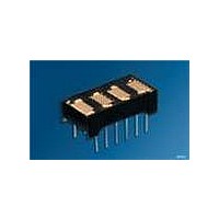
... HDSP2000LP, HDSP2001LP, HDSP2002LP, HDSP2003LP Ordering Information Type Color of Emission HDSP2000LP red HDSP2001LP yellow HDSP2002LP high efficiency red HDSP2003LP green Package Outlines Part No. HDPS200XLP Z OSRAM Pin 1 Indicator 0.51 (0.020) 12 pl. 2.54 (0.100) ±0.13 (0.005) 10 pl., non cum. 17.75 (0.699) max. 4.44 (0.175) 2.11 (0.083) Tolerance: ± ...

Page 3

... HDSP2000LP, HDSP2001LP, HDSP2002LP, HDSP2003LP Maximum Ratings Parameter Operating temperature range Storage temperature range DC Supply Voltage V Inputs, Data Out and B Column Input Voltage Solder temperature 063“ (1.59 mm) below seating plane, t < 5.0 s Allowable Power Dissipation at 1) Maximum allowable dissipation is derived from V Maximum Allowable Power Dissipation vs ...

Page 4

... HDSP2000LP, HDSP2001LP, HDSP2002LP, HDSP2003LP Recommended Operating Conditions Parameter Supply Voltage Data Out Current, Low State Data Out Current, High State Column Input Voltage, Column On HDSP2000LP Column Input Voltage, Column On, HDSP2001LP/2002LP/2003LP Setup Time Hold Time Width of Clock Clock Frequency Clock Transition Time 1) See Figure „ ...

Page 5

... HDSP2000LP, HDSP2001LP, HDSP2002LP, HDSP2003LP Optical Characteristics Red HDSP2000LP Description Peak Luminous Intensity per LED (Character Average) Peak Wavelength 2) Dominant Wavelength Yellow HDSP2001LP Description Peak Luminous Intensity per LED (Character Average) Peak Wavelength 2) Dominant Wavelength High Efficiency Red HDSP2002LP Description Peak Luminous Intensity per LED ...

Page 6

... HDSP2000LP, HDSP2001LP, HDSP2002LP, HDSP2003LP Block Diagram Blanking Control, Rows Serial Data Input Clock Contrast Enhancement Filters Display Color Red Panelgraphic Dark Red 63 HDSP2000LP Panelgraphic Ruby Red 60 Chequers Red 118 Plexiglass 2423 Yellow Panelgraphic Yellow 27 HDSP2001LP HER Panelgraphic Ruby Red 60 HDSP2002LP Chequers Red 112 ...

Page 7

... HDSP2000LP, HDSP2001LP, HDSP2002LP, HDSP2003LP Thermal Considerations The small alphanumeric displays are hybrid LED and CMOS assemblies that are designed for reliable operation in commercial, industrial, and military environments. Optimum reliability and optical performance will result when the junction temperature of the LEDs and CMOS ICs are kept as low as possible. ...

Page 8

... HDSP2000LP, HDSP2001LP, HDSP2002LP, HDSP2003LP Optical Considerations The light output of the LEDs is inversely related to the LED diode’s junction temperature as shown in Figure „Normalized Luminous Intensity vs. Junction Temperature“. For optimum light output, keep the thermal resistance of the socket or PC board as low as possi- ble ...

Page 9

... HDSP2000LP, HDSP2001LP, HDSP2002LP, HDSP2003LP Maximum Character Power Dissipation 1 1 3.5 V, COL LEDs on per Character Character Power Dissipation 2 3 COL COL 1.5 Duty Factor = 5% 1.0 0 LEDs on per Character 2009-03-31 Soldering Considerations The HDSP200xLP can be hand soldered using a grounded iron IDDG5330 set to 260° ...

Page 10

... HDSP2000LP, HDSP2001LP, HDSP2002LP, HDSP2003LP Revision History: 2009-03-31 Previous Version: 2008-09-03 Page Subjects (major changes since last revision) all Lead free device update of outline drawing 2 ordering code corrected Cleaning the Displays IMPORTANT— Do not use cleaning agents containing alcohol of any type with this display. The least offensive cleaning solution is hot D.l. water (60° ...

Related keywords