1-66098-8 TE Connectivity, 1-66098-8 Datasheet - Page 4
1-66098-8
Manufacturer Part Number
1-66098-8
Description
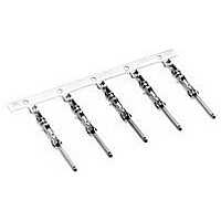
Contact PIN Crimp ST Cable Mount Strip
Manufacturer
TE Connectivity
Series
Type III+r
Specifications of 1-66098-8
Connector Type
Connector Circular
Contact Type
Signal
Contact Material
Brass
Contact Plating
Tin Over Nickel
Gender
PIN
Termination Method
Crimp
Insulation Support
Yes
Termination Method To Wire/cable
Crimp
Wire/cable Type
Discrete Wire
Grade
Commercial
High Current
No
Termination End Plating
Tin
Pin Diameter (mm [in])
1.57 [0.062]
Wire Range (mm [awg])
0.80-1.40² [18-16]
Spring Material
Stainless Steel
Used With
G Series Connectors, M Series Connectors, CPC Connectors
Contact Classification
Signal
Contact Plating, Mating Area, Material
Tin
Contact Base Material
Brass
Contact Size
16
Rohs/elv Compliance
RoHS compliant, ELV compliant
Lead Free Solder Processes
Not relevant for lead free process
Rohs/elv Compliance History
Always was RoHS compliant
Accepts Wire Insulation Diameter, Range (mm [in])
2.03 – 2.54 [0.080 – 0.100]
Applies To
Wire/Cable
Test Current (a)
13.0
Packaging Method
Strip
Lead Free Status / Rohs Status
RoHS Compliant part
Available stocks
Company
Part Number
Manufacturer
Quantity
Price
Company:

Part Number:
1-66098-8
Manufacturer:
TE
Quantity:
16 000
Company:
Part Number:
1-66098-8
Manufacturer:
AMP
Quantity:
35 000


4
Current Rating
Verification
Catalog 82045
Revised 06-08
www.tycoelectronics.com
Dimensions are in millimeters
and inches unless otherwise
specified. Values in brackets are
equivalent U.S. Customary Units.
AMP Metrimate
Pin and Socket Connectors
Performance Characteristics
Can a contact rated at
10 amperes carry 10 amperes?
Maybe yes, but probably not.
The reason lies in the test
conditions used to rate the
contact. If these conditions do
not adequately reflect the
application conditions, the
actual allowable current lev-
els may be lower than speci-
fied levels. For example,
many manufacturers, includ-
ing Tyco Electronics, test a
single contact in air. This
gives an accurate measure of
the basic current-carrying
capacity of the contact. Use
the contact alone in air and it
can certainly carry 10
amperes. Use it in a multi-
position connector sur-
rounded by other
current-carrying contacts or
in high ambient tempera-
tures, and the contact should
carry less current.
Similarly, as the contact ages
and stress relaxation, environ-
mental cycling, and other
degradation factors take their
toll, the contact's current-car-
rying capacity decreases. A
prudent design must set cur-
rent levels for such end-of-
design-life (EODL)
conditions.
Practical current-carrying
capacity is not an absolute,
but an application-dependent
condition.
New Method Simplifies
Ratings
To help the designer set the
appropriate current level,
Tyco Electronics has devel-
oped a method of specifying
current-carrying capacity.
This method takes into
account the various applica-
tion factors that influence
current rating.
Dimensions are shown for
reference purposes only.
Specifications subject
to change.
The method can be
summarized as follows:
•
•
•
•
Temperature
One other factor influencing
current levels is the maximum
operating temperature, for
example, 105°C. If the appli-
cation has a high ambient
temperature (over 75°C) the
contact's T-rise is limited by
the maximum operating tem-
perature. For example, an
application temperature of
90°C limits the contact T-rise
to 15°C. Since current pro-
duces heat (the I
current must be lowered to
limit the T-rise.
A contact's T-rise depends
not only on its I
ing, but also on its ability to
dissipate the heat. Consider a
contact in a multi-contact
housing. Joule heating in
multiple contacts will raise
the local ambient tempera-
ture. Since the contact will
not be able to dissipate its
own heat as well by convec-
tion, the maximum
T-rise will be realized at a
lower current level. Conse-
quently, the allowable current
level must be lower to main-
tain an acceptable T-rise.
The contact is aged to
EODL conditions by dura-
bility cycling, thermal
cycling, and environmental
exposure.
The contact's resistance
stability is verified.
The current necessary to
produce the specified tem-
perature rise is measured.
This T-rise is usually 30°C.
A rating factor is deter-
mined to allow derating of
multiple contacts in the
same housing and for dif-
ferent conductor sizes.
USA: 1-800-522-6752
Canada: 1-905-470-4425
Mexico: 01-800-733-8926
C. America: 52-55-5-729-0425
(Continued)
NOTE: All part numbers
are RoHS Compliant
2
R Joule heat-
2
R law), the
For a given connector, the
current level will be set by
the loading density. A con-
nector containing 50% cur-
rent-carrying contacts will
permit higher currents (per
contact) than a connector
will at 75% loading. The load-
ing percentage assumes an
even distribution of contacts
within the housing. If all 10
contacts are grouped
together in one section of a
20-position connector, the
loading density may
approach 100%.
The Importance of EODL
As stated, T-rise in a contact
depends on both resistance
and current. As it ages, a
contact's resistance will
increase. The contact
designer will specify a maxi-
mum resistance for the con-
tact, this level is the
end-of-design-life resistance.
Before the contact is tested
for current, Tyco Electronics
subjects it to a sequence of
tests that exercise many
major failure mechanisms and
thereby simulates EODL con-
ditions. Conditioning includes
mating cycling, industrial
mixed-flowing gases, humid-
ity and temperature cycling,
and vibration to sequentially
introduce wear, corrosion,
stress relaxation, and
mechanical disturbance.
Presentation
The presentation of current-
carrying capacity in Tyco
Electronics product specifica-
tions includes two parts:
•
First, a base curve showing
current levels versus T-rise
for a single circuit and the
largest wire size. This rep-
resents the maximum cur-
rent capacity of the
South America: 55-11-3611-1514
Hong Kong: 852-2735-1628
Japan: 81-44-844-8013
UK: 44-141-810-8967
Related parts for 1-66098-8
Image
Part Number
Description
Manufacturer
Datasheet
Request
R

Part Number:
Description:
RELAY SSR SCR OUT 125A 480VAC
Manufacturer:
TE Connectivity
Datasheet:

Part Number:
Description:
CONN PIN .062 14-18AWG AU CRIMP
Manufacturer:
Tyco Electronics
Datasheet:

Part Number:
Description:
CONN SOCKET 22-26AWG GOLD CRIMP
Manufacturer:
Tyco Electronics
Datasheet:

Part Number:
Description:
CONN SKT .062 14-18AWG TIN CRIMP
Manufacturer:
Tyco Electronics
Datasheet:

Part Number:
Description:
CONN PIN 18-14AWG TIN CRIMP
Manufacturer:
Tyco Electronics
Datasheet:

Part Number:
Description:
Manufacturer:
TE Connectivity
Datasheet:

Part Number:
Description:
Manufacturer:
TE Connectivity
Datasheet:

Part Number:
Description:
Manufacturer:
TE Connectivity
Datasheet:

Part Number:
Description:
Manufacturer:
TE Connectivity
Datasheet:

Part Number:
Description:
Manufacturer:
TE Connectivity
Datasheet:

Part Number:
Description:
PLCC SOCKET, 68POS, THROUGH HOLE
Manufacturer:
TE Connectivity
Datasheet:

Part Number:
Description:
DIP SOCKET, 20POS, THROUGH HOLE
Manufacturer:
TE Connectivity
Datasheet:

Part Number:
Description:
Conn Unshrouded Header HDR 16 POS 2.54mm Solder ST Thru-Hole
Manufacturer:
TE Connectivity
Datasheet:

Part Number:
Description:
FFC/FPC CONNECTOR, RECEPTACLE 16POS 1ROW
Manufacturer:
TE Connectivity
Datasheet:

Part Number:
Description:
Connector Accessories CPC Clamp Thermoplastic Black Individual
Manufacturer:
TE Connectivity
Datasheet: