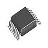
LMH6739MQ National Semiconductor, LMH6739MQ Datasheet - Page 9

LMH6739MQ
Manufacturer Part Number
LMH6739MQ
Description
Manufacturer
National Semiconductor
Datasheet
1.LMH6739MQ.pdf
(12 pages)
Specifications of LMH6739MQ
Power Supply Requirement
Single
Single Supply Voltage (typ)
9V
Dual Supply Voltage (typ)
Not RequiredV
Single Supply Voltage (min)
8V
Single Supply Voltage (max)
12V
Dual Supply Voltage (min)
Not RequiredV
Dual Supply Voltage (max)
Not RequiredV
Operating Temperature Classification
Industrial
Mounting
Surface Mount
Pin Count
16
Package Type
SSOP
Lead Free Status / RoHS Status
Not Compliant
Available stocks
Company
Part Number
Manufacturer
Quantity
Price
Part Number:
LMH6739MQ
Manufacturer:
NS/国半
Quantity:
20 000
Part Number:
LMH6739MQX
Manufacturer:
TI/德州仪器
Quantity:
20 000
UNITY GAIN COMPENSATION
With a current feedback Selectable Gain Buffer like the
LMH6739, the feedback resistor is a compromise between
the value needed for stability at unity gain and the optimized
value used at a gain of two. The result of this compromise is
substantial peaking at unity gain. If this peaking is undesirable
a simple RC filter at the input of the buffer will smooth the
frequency response shown as Figure 4. Figure 5 shows the
results of a simple filter placed on the non-inverting input. See
Figure 6 and Figure 7 for another method for reducing unity
gain peaking.
FIGURE 7. Frequency Response for Circuit in Figure 6
FIGURE 6. Alternate Unity Gain Compensation
FIGURE 8. Decoupling Capacitive Loads
20104137
20104138
20104107
9
DRIVING CAPACITIVE LOADS
Capacitive output loading applications will benefit from the
use of a series output resistor R
of a series output resistor, R
put under capacitive loading. Capacitive loads of 5 to 120 pF
are the most critical, causing ringing, frequency response
peaking and possible oscillation. The charts “Suggested
R
a series output resistor for mitigating capacitive loads. The
values suggested in the charts are selected for .5 dB or less
of peaking in the frequency response. This gives a good com-
promise between settling time and bandwidth. For applica-
tions where maximum frequency response is needed and
some peaking is tolerable, the value of R
slightly from the recommended values.
LAYOUT CONSIDERATIONS
Whenever questions about layout arise, use the evaluation
board as a guide. The LMH730275 is the evaluation board
supplied with samples of the LMH6739.
To reduce parasitic capacitances ground and power planes
should be removed near the input and output pins. Compo-
nents in the feedback loop should be placed as close to the
device as possible. For long signal paths controlled
impedance lines should be used, along with impedance
matching elements at both ends.
Bypass capacitors should be placed as close to the device as
possible. Bypass capacitors from each rail to ground are ap-
plied in pairs. The larger electrolytic bypass capacitors can be
located farther from the device, the smaller ceramic capaci-
tors should be placed as close to the device as possible. The
LMH6739 has multiple power and ground pins for enhanced
supply bypassing. Every pin should ideally have a separate
bypass capacitor. Sharing bypass capacitors may slightly de-
grade second order harmonic performance, especially if the
supply traces are thin and /or long. In Figure 1 and Figure 2
C
ic distortion. Another option to using C
μF and .1 μF ceramic capacitors for each supply bypass.
VIDEO PERFORMANCE
The LMH6739 has been designed to provide excellent per-
formance with production quality video signals in a wide va-
riety of formats such as HDTV and High Resolution VGA.
NTSC and PAL performance is nearly flawless. Best perfor-
mance will be obtained with back terminated loads. The back
termination reduces reflections from the transmission line and
effectively masks transmission line and other parasitic ca-
pacitances from the amplifier output stage. Figure 4 shows a
typical configuration for driving a 75Ω Cable. The amplifier is
configured for a gain of two to make up for the 6 dB of loss in
R
OUT
SS
OUT
is optional, but is recommended for best second harmon-
.
vs. Cap Load” give a recommended value for selecting
OUT
, to stabilize the amplifier out-
OUT
. Figure 8 shows the use
SS
is to use pairs of .01
OUT
can be reduced
www.national.com


