DJR2-110A Crouzet USA, DJR2-110A Datasheet
DJR2-110A
Manufacturer Part Number
DJR2-110A
Description
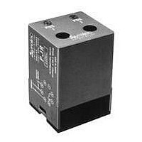
ALTERNATING LOAD RELAY, DPDT, 10A
Manufacturer
Crouzet USA
Datasheet
1.PJR110A.pdf
(2 pages)
Specifications of DJR2-110A
Contact Current Max
10A
Contact Voltage Ac Nom
250V
Contact Voltage Dc Nom
250V
Contact Configuration
DPDT
Relay Mounting
DIN Rail
Average Power Consumption
5VA
External Height
75mm
Lead Free Status / RoHS Status


CONTROLS
JR SERIES
ALTERNATING RELAY
UL listed
• Duplex Alternating Control
• SPDT or DPDT Control Relay
• 10 Amp Rated
• Externally Controlled
The electronic alternating relay is designed to replace mechanical
style devices used in control applications requiring a duplexing
or alternating action of the control circuits to operate pumps,
compressors, etc. This is achieved by activating a control switch
which is common to one side of the input control voltage. The output
contact of the relay(s) change state when this switch is opened
SPECIFICATIONS:
Input . . . . . . . . . . . . . . . . . . . . . . . . 24 VAC/DC, 110, 220 VAC
Maximum power consumption . . . 24 VAC: 1.5 VA
Output . . . . . . . . . . . . . . . . . . . . . . SPDT 10 A resistive
Minimum pulse
Contact material
Maximum loading
Maximum switching voltage . . . . . 250 VAC
Relay maximum power rating . . . . 2200 VA
Mechanical life of relay . . . . . . . . . 3 x 10
Electrical life of relay . . . . . . . . . . . 2 x 10
Operating temperature . . . . . . . . . 14°F to 140°F
Weight . . . . . . . . . . . . . . . . . . . . . . 2.8 oz. (100g)
ORDERING INFORMATION:
L = 11 pin plug-in
P = 8 pin plug-in
MOUNTING
204 Airline Drive, Suite 300, Coppell, Texas 75019 / Tel: (800) 677-5311 / FAX: (800) 677-3865 / www.crouzet-usa.com
CSA recognized
. . . . . . . . . . . . . . . 30 ms
. . . . . . . . . . . . . . AgCdO
. . . . . . . . . . . . . 10 A AC resistive 8 A DC inductive
± 15%, 50/60 Hz
110 VAC: 5 VA
220 VAC: 11 VA
DPDT 10 A resistive
DPDT 10 A crosswired
6
5
operations
at 2200 VA resistive load
Products and specifications subject to change without notice.
MOUNTING
Consult factory for application assistance.
L
250 VDC
80 W
-10°C to +60°C
JR2 = DPDT (LJRZ only)
JR = SPDT
JRX = DPDT crosswired
SERIES
SERIES
(on de-energization of the control circuit). When the control initiate
switch is actuated and released or opened, the relay will change
state. The next time the initiate switch is actuated and released it
will change back to its original state. Two red LED’s located on the
top of the dust resistant enclosure provide the status of the relay.
WIRING DIAGRAM:
JR2
3
2
PJR
1
4
* INITIATE SWITCH must be isolated from other circuits
5
8
INITIATE
SWITCH
6
7
*
INPUT POWER
110A
INITIATE SWITCH*
3
2
PJRX
1
4
5
8
6
7
CONTROLS
24A = 24 VAC/DC
110A = 110 VAC
220A = 220 VAC
INPUT POWER
3
4
2
LJR2
5
1
INITIATE
6
1 1
SWITCH
7
10
8
9
*
5-11
5
Related parts for DJR2-110A
Image
Part Number
Description
Manufacturer
Datasheet
Request
R

Part Number:
Description:
SCREW SOCKET (OT08PC)
Manufacturer:
Crouzet USA
Datasheet:

Part Number:
Description:
PANEL PLATE FOR 813
Manufacturer:
Crouzet USA
Datasheet:
Part Number:
Description:
Controller; CTD46 Dual Display Temperature, 1/16 DIN, NEMA 4X, 110/220VAC
Manufacturer:
Crouzet USA
Datasheet:

Part Number:
Description:
11R1084
Manufacturer:
Crouzet USA
Datasheet:
Part Number:
Description:
11R1086
Manufacturer:
Crouzet USA
Datasheet:
Part Number:
Description:
11R1087
Manufacturer:
Crouzet USA
Datasheet:
Part Number:
Description:
11R1089
Manufacturer:
Crouzet USA
Datasheet:
Part Number:
Description:
11R1078
Manufacturer:
Crouzet USA
Datasheet:
Part Number:
Description:
11R1079
Manufacturer:
Crouzet USA
Datasheet:
DJR2-110A Summary of contents
Page 1
CONTROLS JR SERIES ALTERNATING RELAY UL listed CSA recognized • Duplex Alternating Control • SPDT or DPDT Control Relay • 10 Amp Rated • Externally Controlled The electronic alternating relay is designed to replace mechanical style devices used in control ...
Page 2
...