TC1270ATVRCTR Microchip Technology, TC1270ATVRCTR Datasheet - Page 18
TC1270ATVRCTR
Manufacturer Part Number
TC1270ATVRCTR
Description
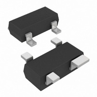
IC,Power Supply Supervisor,TO-253,4PIN,PLASTIC
Manufacturer
Microchip Technology
Type
Simple Reset/Power-On Resetr
Datasheet
1.TC1270ALVRCTR.pdf
(48 pages)
Specifications of TC1270ATVRCTR
Number Of Voltages Monitored
1
Output
Push-Pull, Totem Pole
Reset
Active Low
Reset Timeout
140 ms Minimum
Voltage - Threshold
3.08V
Operating Temperature
-40°C ~ 125°C
Mounting Type
Surface Mount
Package / Case
SOT-143, SOT-143B, TO-253AA
Lead Free Status / RoHS Status
Lead free / RoHS Compliant
Available stocks
Company
Part Number
Manufacturer
Quantity
Price
Company:

Part Number:
TC1270ATVRCTR
Manufacturer:
MICROCHIP
Quantity:
12 000
Part Number:
TC1270ATVRCTR
Manufacturer:
MICROCHIP/微芯
Quantity:
20 000


TC1270A/70AN/71A
TABLE 3-1:
3.1
V
input voltage. Typically, the circuit ground is used.
3.2
V
voltage level that requires monitoring.
3.3
There are three types of Reset output pins. These are:
1.
2.
3.
3.3.1
The RST push-pull output remains low while V
below the reset voltage threshold (V
the RST pin is held low after the device voltage (V
returns to a high level (> V
After the Reset Delay Timer expires, the RST pin will be
driven to the high state.
DS22035C-page 18
Note 1:
(Push-Pull,
active low)
SS
DD
TC1270A
3
2
1
Push-Pull active-low Reset
Push-Pull active-high Reset
Open-Drain active-low Reset, external pull-up
resistor required.
provides the negative reference for the analog
can be used for power supply monitoring or a
Ground Terminal (V
Supply Voltage (V
Reset Output (RST and RST)
—
3
4
The MR pin has an internal weak pull-up (18.5 k typical).
ACTIVE-LOW (RST) - PUSH-PULL
(Open-Drain,
Pin Number
active low)
TC1270AN
PINOUT DESCRIPTION (CONTINUED)
—
—
—
TRIP
active high)
(Push-Pull,
DD
) is typically 280 ms.
TC1271A
3
2
1
SS
)
TRIP
)
). The time that
—
3
4
Sym
V
MR
NC
DD
DD
DD
is
)
Type
—
—
I
Pin
Buffer
Driver
Power Supply Voltage
ST
3.3.2
The RST push-pull output remains high while V
below the Reset voltage threshold (V
that the RST pin is held high after the device voltage
(V
280 ms. After the Reset Delay Timer expires, the RST
pin will be driven to the low state.
3.3.3
The RST open-drain output remains low while V
below the reset voltage threshold (V
the RST pin is held low after the device voltage (V
returns to a high level (> V
time out selected. After the Reset Delay Timer expires,
the RST pin will float.
3.4
The Manual Reset (MR) input pin allows a push button
switch to easily be connected to the system. When the
push button is depressed, it forces a system Reset.
This pin has circuitry that filters noise that may be
present on the MR signal.
The MR pin is active-low and has an internal pull-up
resistor.
—
/
DD
(1)
) returns to a high level (> V
Manual Reset Input Pin
This input allows a push button switch to be
directly connected to a TC1270A/70AN/71A
device’s MR pin, which can be used to force a
system Reset. The input filter ignores noise
pulses that occur on the MR pin.
H = Switch is open (internal pull-up resistor
L = Switch is depressed (shorted to ground).
No Connection
Manual Reset Input (MR)
pulls signal high). State of the RST/RST
pin is determined by other system condi-
tions.
This forces the RST/RST pin Active.
ACTIVE-HIGH (RST) - PUSH-PULL
ACTIVE-LOW (RST) - OPEN-DRAIN
Standard Function
2010 Microchip Technology Inc.
TRIP
) depends on the Reset
TRIP
TRIP
TRIP
). The time that
) is typically
). The time
DD
DD
DD
is
is
)
Related parts for TC1270ATVRCTR
Image
Part Number
Description
Manufacturer
Datasheet
Request
R

Part Number:
Description:
Voltage Supervisor with Manual Reset Input
Manufacturer:
MICROCHIP [Microchip Technology]
Datasheet:

Part Number:
Description:
Manufacturer:
Microchip Technology Inc.
Datasheet:
Part Number:
Description:
Manufacturer:
Microchip Technology Inc.
Datasheet:
Part Number:
Description:
Manufacturer:
Microchip Technology Inc.
Datasheet:
Part Number:
Description:
Manufacturer:
Microchip Technology Inc.
Datasheet:
Part Number:
Description:
Manufacturer:
Microchip Technology Inc.
Datasheet:
Part Number:
Description:
Manufacturer:
Microchip Technology Inc.
Datasheet:
Part Number:
Description:
Manufacturer:
Microchip Technology Inc.
Datasheet:
Part Number:
Description:
Manufacturer:
Microchip Technology Inc.
Datasheet: