SY89321LMG TR Micrel Inc, SY89321LMG TR Datasheet - Page 3
SY89321LMG TR
Manufacturer Part Number
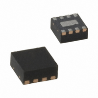
SY89321LMG TR
Description
3.3V 800MHz Ultrasmall Dual LVTTL-to-LVPECL Translator (I Temp, Green)
Manufacturer
Micrel Inc
Series
SY89r
Datasheet
1.SY89321LMG_TR.pdf
(5 pages)
Specifications of SY89321LMG TR
Logic Function
Translator
Number Of Bits
1
Input Type
CML, LVDS, LVPECL
Output Type
LVTTL
Number Of Channels
1
Number Of Outputs/channel
1
Differential - Input:output
Yes/No
Propagation Delay (max)
1.9ns
Voltage - Supply
3 V ~ 3.6 V
Operating Temperature
-40°C ~ 85°C
Package / Case
8-MLF®, QFN
Supply Voltage
3 V ~ 3.6 V
Logic Family
ECL
Logical Function
Translator
Technology
ECL
High Level Output Current
-3mA
Low Level Output Current
24mA
Operating Supply Voltage (typ)
3.3V
Operating Supply Voltage (max)
3.6V
Operating Supply Voltage (min)
3V
Abs. Propagation Delay Time
2.5ns
Mounting
Surface Mount
Pin Count
8
Operating Temperature (min)
-40C
Operating Temperature (max)
85C
Operating Temperature Classification
Industrial
Lead Free Status / RoHS Status
Lead free / RoHS Compliant
Data Rate
-
Lead Free Status / Rohs Status
Compliant
Other names
576-2954-2
SY89321LMG TR
SY89321LMGTR
SY89321LMGTR
SY89321LMG TR
SY89321LMGTR
SY89321LMGTR


Micrel, Inc.
Absolute Maximum Ratings
Supply Voltage (V
Input Voltage (V
LVTT Output Current (I
Current (V
Lead Temperature (soldering, 20 sec.) ................... +260 C
Storage Temperature (T
V
Symbol
I
I
V
V
V
Symbol
V
V
V
V
V
V
V
I
I
Note 1.
Note 2.
Note 3.
Note 4.
Note 5.
M9999-060208
hbwhelp@micrel.com or (408) 955-1690
OS
CC
IH
IL
CC
OH
OL
CC
IH_LVPECL
IL_LVPECL
BB
IH_CML
IL_CML
IH_LVDS
IL_LVDS
LVTTL DC ELECTRICAL CHARACTERISTICS
LVPECL/CML/LVDS DC ELECTRICAL CHARACTERISTICS
Continuous ............................................................. 50mA
Surge .................................................................... 100mA
Source or sink current on V
= +3.3V 10%
= +3.3V 10%; T
Permanent device damage may occur if absolute maximum ratings are exceeded. This is a stress rating only and functional operation is not
implied at conditions other than those detailed in the operational sections of this data sheet. Exposure to absolute maximum ratlng conditions
for extended periods may affect device reliability.
The data sheet limits are not guaranteed if the device is operated beyond the operating ratings.
Due to the limited drive capability use for input of the same package only.
Package thermal resistance assumes exposed pad is soldered (or equivalent) to the devices most negative potential (GND) on the PCB.
Max. limit only applicable for short durations, not for continuous operation!
BB
)
Parameter
Output Short Circuit Current
Power Supply Current
Output HIGH Voltage
Output LOW Voltage
Parameter
Input HIGH Voltage
Input LOW Voltage
Bias Voltage
Input HIGH Voltage
Input LOW Voltage
Input HIGH Voltage
Input LOW Voltage
Input HIGH Current
Input LOW Current IN
Input LOW Current /IN
IN
CC
) ......................................... –0.5V to V
A
) .................................. –0.5V to +3.8V
= –40 C to +85 C unless otherwise noted.
OUT
S
) ....................... –65 C to +150 C
)
BB
, Note 3 ................ 1.5mA
(Note 1)
Condition
V
I
I
Condition
OH
OL
OUT
= 24mA
= –3.0mA
= 0V, Note 5
CC
3
Operating Ratings
Supply Voltage (V
Ambient Temperature (T
Package Thermal Resistance, Note 4
MLF
MLF
Still-Air ................................................................. 93 C/W
500lfpm ............................................................... 87 C/W
Junction-to-Board ................................................ 60 C/W
®
®
(
(
JA
JB
)
)
CC
) ...................................... 3.0V to 3.6V
V
V
V
V
V
CC
CC
CC
CC
CC
–300
Min
1.4
1.1
0.5
–1.165
–1.810
–0.400
–0.800
A
—
–1.38 V
(Note 2)
) ......................... –40 C to +85 C
Min
–80
2.0
—
—
CC
Typ
—
—
—
—
—
—
—
—
—
–1.32 V
Typ
14
—
—
—
V
V
V
CC
CC
IH
Precision Edge
CC
Max
V
–0.400
150
1.5
1.2
–0.880
–1.475
—
—
–275
–1.26
Max
CC
0.5
20
—
SY89321L
Units
Units
mA
mA
V
V
V
V
V
V
V
V
V
A
A
A
®
Related parts for SY89321LMG TR
Image
Part Number
Description
Manufacturer
Datasheet
Request
R

Part Number:
Description:
Manufacturer:
Micrel Inc
Datasheet:
Part Number:
Description:
Manufacturer:
Micrel Inc
Datasheet:
Part Number:
Description:
Manufacturer:
Micrel Inc
Datasheet:
Part Number:
Description:
Manufacturer:
Micrel Inc
Datasheet:
Part Number:
Description:
Manufacturer:
Micrel Inc
Datasheet:
Part Number:
Description:
Manufacturer:
Micrel Inc
Datasheet:
Part Number:
Description:
Manufacturer:
Micrel Inc
Datasheet:
Part Number:
Description:
Manufacturer:
Micrel Inc
Datasheet:
Part Number:
Description:
Manufacturer:
Micrel Inc
Datasheet:
Part Number:
Description:
Manufacturer:
Micrel Inc
Datasheet:
Part Number:
Description:
Manufacturer:
Micrel Inc
Datasheet:
Part Number:
Description:
Manufacturer:
Micrel Inc
Datasheet:
Part Number:
Description:
Manufacturer:
Micrel Inc
Datasheet:
Part Number:
Description:
Manufacturer:
Micrel Inc
Datasheet: