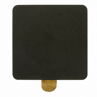
MP1040-200 Laird Technologies, MP1040-200 Datasheet

MP1040-200
Manufacturer Part Number
MP1040-200
Description
FERRITE EMI PLT 26.42X26.42X1.91
Manufacturer
Laird Technologies
Series
Stewardr
Datasheet
1.MP0315-200.pdf
(1 pages)
Specifications of MP1040-200
Filter Type
Ferrite Plate
Size / Dimension
1.040" L x 1.040" W x 0.075" H (26.42mm x 26.42mm x 1.91mm)
Product
Ferrite Plates
Operating Temperature Range
- 40 C to + 125 C
Package / Case
1040
Termination Style
Plate
Lead Free Status / RoHS Status
Lead free / RoHS Compliant
Other names
240-2267
Available stocks
Company
Part Number
Manufacturer
Quantity
Price
Company:
Part Number:
MP1040-200
Manufacturer:
STEWARD
Quantity:
503
Ferrite EMI Disks and Plates
Ferrite disc & plate samples are available with temporary adhesive so the sample part can be tested in numerous locations.
Production parts have permanent adhesive. Custom parts available.
SIP-BRO-DISKPLATE-0208
Laird Technologies,
soldering process, a ferrite disk or plate can be installed directly on the source of EMI (such as active devices or unwanted antennas).
Features:
• Easy installation • Each part for volume production is provided with permanent, double sided 3,5 mil acrylic adhesive with 218 oz./inch
and sample kits are available with removable and reusable adhesive for "trial and error" testing • Variety of sizes offered • For frequencies above 250 MHz,
H series material is generally better than M series material • Custom parts also available.
Applications:
•
(Inductive coupling occurs when the ferrite affects the conducted wave form leaving the active component. The rise time of the wave form is effectively slowed
by the ferrite, and the overshoot and associated ringing are attenuated. EMI shielding occurs when the ferrite absorbs the radiated emissions from active com-
ponents, effectively protecting other boards or components in the vicinity from radiated contamination). • Can be used to locate unwanted EMI antennas. •
Flat Flex & Ribbon cables. • Can also provide retrofit, auxiliary EMI attenuation.
Example Application Graph Explanation:
The zero line on the graph represents the base line noise recorded for an unprotected microprocessor. The curves (dB down) represent the performance of the
Laird Technologies' ferrite plates relative to the baseline. The addition of the ferrite plates to the top of the processor in this specific application exhibits up to
a 5 dB EMI reduction relative to the unprotected part. In the example application graph above, the ferrite plate MP1040-100 exhibits up to a 1 dB advantage
over the HP1040-100 from 1-100 MHz, while the HP1040-100 exhibits a 0,5 dB advantage between 200 and 400 MHz. Performance can vary with different
sizes, materials, processors and applications.
Test Conditions:
• Microprocessor — Motorola HC16 • Clock Speed — 16 MHz • Mini-Tem radiated emissions using an sbec3a tem cell board
• Sweep Rate — 100 s • No. of Sweeps — 1 • Resolution BW — 10 kHz • Video BW — 30 kHz • Amplification — 31,00 dB
PArT NUMBErING SYSTEM
H - MATErIAL
M - MATErIAL
Laird Technologies,
MP
- 4
Disk
- 1
HP
- 3
- 5
- 6
- 2
0
1
1
H
MP1040-100 and HP1040-100
EXAMPLE APPLICATION
Ferrite Disks and Plates provide a simple, cost-effective solution for radiated and inductively-coupled electromagnetic interference. After the PC board
M - DISk
P - PLATE
ferrite disks and plates can be utilized either as inductively-coupled components or EMI shields on PC board components and traces.
M
10
Frequency MHz
PArT SIZE
IDENTIFICATION
0787
Plate
100
THICkNESS
CODE
100
www.lairdtech.com
MP 1040-100
HP 1040-100
1000
MM0650-100
MM0787-100
MM0787-200
MM1400-200
MM1400-300
HM0787-100
HM0787-200
HM1400-200
HM1400-300
MP0315-200
MP0350-000
MP0433-000
MP0512-200
MP0590-200
MP0591-200
MP0760-100
MP1040-100
MP1040-200
MP1040-300
MP1496-000
HP1040-100
HP1040-200
NUMBEr
PArT
(inches)
(0,787)
(0,787)
(1,400)
(1,400)
(0.650)
(0,787)
(0,787)
(1,400)
(1,400)
(1,040)
(1,040)
(0,315)
(1,040)
(0,433)
(0,512)
(0,827)
(0,591)
(0,760)
(1,040)
(1,040)
(1,040)
(1,496)
mm
20,00
20,00
35,56
35,56
16,51
20,00
20,00
35,56
35,56
26,42
26,42
26,42
11,00
13,00
21,00
15,00
19,30
26,42
26,42
26,42
38,00
8,00
A
(inches)
(1,040)
(1,040)
(0,315)
(0,350)
(0,433)
(0,512)
(0,591)
(0,591)
(0,760)
(1,040)
(1,040)
(1,040)
(1,496)
mm
26,42
26,42
11,00
13,00
15,00
15,00
19,30
26,42
26,42
26,42
38,00
8,00
8,89
B
2
adhesion. • Samples
(inches)
(0,050)
(0,075)
(0,075)
(0,100)
(0,050)
(0,050)
(0,075)
(0,075)
(0,100)
(0,050)
(0,075)
(0,079)
(0,050)
(0,077)
(0,079)
(0,079)
(0,079)
(0,050)
(0,050)
(0,075)
(0,089)
(0,079)
mm
1,27
1,91
1,91
2,54
1,27
1,27
1,91
1,91
2,54
1,27
1,91
2,00
1,27
1,96
2,00
2,00
2,00
1,27
1,27
1,91
2,25
2,00
C


