PIC32MX320F064HT-40I/MR Microchip Technology, PIC32MX320F064HT-40I/MR Datasheet - Page 25
PIC32MX320F064HT-40I/MR
Manufacturer Part Number
PIC32MX320F064HT-40I/MR
Description
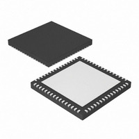
64 KB Flash, 16 KB RAM, 40 MHz, 10-Bit ADC 64 QFN 9x9x0.9mm T/R
Manufacturer
Microchip Technology
Series
PIC® 32MXr
Datasheets
1.MA320002.pdf
(208 pages)
2.PIC32MX320F032H-40IPT.pdf
(48 pages)
3.PIC32MX320F032H-40IPT.pdf
(66 pages)
4.PIC32MX320F032H-40IPT.pdf
(22 pages)
Specifications of PIC32MX320F064HT-40I/MR
Core Processor
MIPS32® M4K™
Core Size
32-Bit
Speed
40MHz
Connectivity
I²C, IrDA, LIN, PMP, SPI, UART/USART
Peripherals
Brown-out Detect/Reset, POR, PWM, WDT
Number Of I /o
53
Program Memory Size
64KB (64K x 8)
Program Memory Type
FLASH
Ram Size
16K x 8
Voltage - Supply (vcc/vdd)
2.3 V ~ 3.6 V
Data Converters
A/D 16x10b
Oscillator Type
Internal
Operating Temperature
-40°C ~ 85°C
Package / Case
64-VFQFN, Exposed Pad
Processor Series
PIC32MX3xx
Core
MIPS
Data Bus Width
32 bit
Data Ram Size
16 KB
Interface Type
EUART, I2C, SPI
Maximum Clock Frequency
40 MHz
Number Of Programmable I/os
53
Number Of Timers
5
Maximum Operating Temperature
+ 85 C
Mounting Style
SMD/SMT
3rd Party Development Tools
52713-733, 52714-737
Development Tools By Supplier
PG164130, DV164035, DV244005, DV164005, DM320001, DM320002, MA320001
Minimum Operating Temperature
- 40 C
On-chip Adc
10 bit, 16 Channel
Lead Free Status / RoHS Status
Lead free / RoHS Compliant
Eeprom Size
-
Lead Free Status / Rohs Status
Details


PIC32MX Starter Kit Tutorial
The tutorial program includes the Debug Print Library, which facilitates print functional-
ity. A peripheral library header file for flashing the LEDs is also included. The header
file for print functionality is
.
db_utils.h
Depending on the macro definition given in the print header file, the debug print macros
will be expanded. The print functionality in the tutorial is routed to the Output window
on the MPLAB PIC32MX tab in the interface window. In order to achieve this, the
macro definition “PIC32_STARTER_KIT” is added to the MPLAB C Compiler for PIC32
options.
As the program runs, the Output window (Figure 2-14) tracks the progress.
FIGURE 2-14:
OUTPUT WINDOW
After printing the menu, the application displays a prompt that requests your input, see
Figure 2-15.
FIGURE 2-15:
TARGET IN WINDOW
Type your choice into the Enter Information to be Sent to Target box, and click Send.
The program responds according to the menu entry. Watch the LEDs on the starter kit
board. If your entry is incorrect, the LEDs will toggle once.
© 2009 Microchip Technology Inc.
DS61144D-page 21
Related parts for PIC32MX320F064HT-40I/MR
Image
Part Number
Description
Manufacturer
Datasheet
Request
R

Part Number:
Description:
Manufacturer:
Microchip Technology Inc.
Datasheet:
Part Number:
Description:
Manufacturer:
Microchip Technology Inc.
Datasheet:
Part Number:
Description:
Manufacturer:
Microchip Technology Inc.
Datasheet:
Part Number:
Description:
Manufacturer:
Microchip Technology Inc.
Datasheet:
Part Number:
Description:
Manufacturer:
Microchip Technology Inc.
Datasheet:
Part Number:
Description:
Manufacturer:
Microchip Technology Inc.
Datasheet:
Part Number:
Description:
Manufacturer:
Microchip Technology Inc.
Datasheet:
Part Number:
Description:
Manufacturer:
Microchip Technology Inc.
Datasheet: