28A2738-0A2 Laird Technologies, 28A2738-0A2 Datasheet - Page 21
28A2738-0A2
Manufacturer Part Number
28A2738-0A2
Description
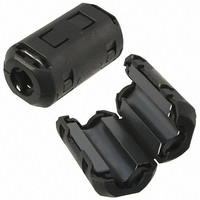
FERRITE EMI SPLIT/SNAP-ON CORE
Manufacturer
Laird Technologies
Series
28Ar
Type
Core-Splitr
Datasheet
1.28A2005-0A2.pdf
(28 pages)
Specifications of 28A2738-0A2
Filter Type
Round Cable, Snap On
Shape
Cylindrical
Frequency
100MHz
Impedance
233 Ohm
Package / Case
19.70mm O.D. x 9.00mm I.D. x 35.10mm L
Test Frequency
100 MHz
Product
Clamp-On Ferrite Suppressors
Termination Style
Cable Snap
Diameter, Cable
0.315 "
Impedance, At 100 Mhz
233 Ohms
Impedance, At 25 Mhz
109 Ohms
Impedance, At 300 Mhz
366 Ohms
Material, Core
28
Special Features
Black Plastic Snap-On Case
Termination
Cable
Dimensions
19.7 mm Dia. x 35.1 mm L
Lead Free Status / RoHS Status
Lead free / RoHS Compliant
Lead Free Status / RoHS Status
Lead free / RoHS Compliant, Lead free / RoHS Compliant
Other names
240-2603


www.lairdtech.com
FERRITE EMI CABLE CORES
BROADBAND FERRITE EMI CORES
FOR RIBBON & FLEX CABLES
** The “D” & “E” dimensions for 28S, split, two piece cores must be doubled for total assembled dimensions.
“D” & “E” dimensions shown for hinged case parts are for a complete assembly.
PLASTIC CLIP DIAGRAM
Laird Techologies offers a selection of broadband “split” ribbon and flex cores for retrofit and post-assembly operations. Simi-
lar in performance to one-piece core designs, these split ferrite cores provide excellent differential and common mode EMI
suppression on flat cable assemblies. Lightweight, inexpensive metal or plastic end clips and cases provide secure closure of
the ferrite onto the flat cable.
PART NUMBERING SYSTEM EXAMPLE
28S2012-0M0
28S2023-0M0
28S0670-000
28S2001-0*0
28S2001-2A2
28S2011-0*0
28S2022-0*0
28S2827-210
Material
NUMBER
Type
28
PART
Product
Code
S
page
# on
Fig
22
2
1
3
1
1
1
1
1
Part Size
0670
*Available
Code
Hinged Case
End Clip
Types
M, P
M, P
M, P
NA
NA
M
M
Dimension Code
(Usually Length)
(0.670)
(2.500)
(2.641)
(3.000)
(3.500)
(1.775)
(1.500)
(0.827)
17.02
63.50
67.08
76.20
88.90
45.09
38.10
21.00
Selected
A
-0
DIMENSIONS mm (inches)
(0.492)
(2.050)
(2.116)
(2.570)
(3.080)
(1.355)
(1.050)
(0.669)
12.50
52.07
53.75
65.28
78.23
34.42
26.67
17.00
B
Case or Clip
(0.590)
(1.125)
(1.084)
(1.125)
(1.125)
(1.125)
(1.000)
(0.473)
14.99
28.58
27.53
28.58
28.58
28.58
25.40
12.01
Code
C*
0*
(0.134)
(0.250)
(0.656)
(0.250)
(0.255)
(0.250)
(0.250)
(0.157)
16.66
3.40
6.35
6.35
6.48
6.35
6.35
3.99
D
Additional Part
Description
(0.020)
(0.033)
(0.075)
(0.033)
(0.033)
(0.033)
(0.033)
(0.037)
0.51
0.84
1.91
0.84
0.84
0.84
0.84
0.94
E
0
METAL CLIP DIAGRAM
@ 25
MHz
100
100
100
115
60
80
80
43
Typical Impedance
(Z) in Ohms (Ω)
(side view)
*
*
*
*
0
M
P
A
@ 100
MHz
= No End Clip
= Plastic Clip
= Hinged Case
150
280
230
280
240
250
250
120
= Metal Clip
@ 300
MHz
310
590
480
600
630
550
520
270
Custom parts
with double sided
mounting tape
and hinged case
are available.
*Broadband
(28) ribbon and
flex cable cores
are sorted by
slot width on
pages 23 & 24
and sorted by
impedance on
pages 25 & 26.
21
Related parts for 28A2738-0A2
Image
Part Number
Description
Manufacturer
Datasheet
Request
R

Part Number:
Description:
FERRITE EMI SPLIT/SNAP-ON CORE
Manufacturer:
Laird Technologies
Datasheet:

Part Number:
Description:
Bluetooth Serial Module Development Kit
Manufacturer:
Laird Technologies
Part Number:
Description:
BLUETOOTH MODULE DEVELOPMENT KIT
Manufacturer:
Laird Technologies
Part Number:
Description:
Bluetooth 2.0 AT Data Module, Internal Antenna Development Kit
Manufacturer:
Laird Technologies

Part Number:
Description:
BLUETOOTH EVAL BOARD BTM511
Manufacturer:
Laird Technologies
Datasheet:

Part Number:
Description:
Bluetooth / 802.15.1 Modules & Development Tools BLUETTH Multimed MODLE, No ANT DEVKIT
Manufacturer:
Laird Technologies
Datasheet:

Part Number:
Description:
DEV KIT PRM122
Manufacturer:
Laird Technologies
Datasheet:
Part Number:
Description:
DEV KIT PRM123
Manufacturer:
Laird Technologies
Datasheet:

Part Number:
Description:
KIT FOR PRM112
Manufacturer:
Laird Technologies
Datasheet:
Part Number:
Description:
DEV KIT PRM121
Manufacturer:
Laird Technologies
Datasheet:

Part Number:
Description:
CHOKE COMMON MODE 110 OHMS SMD
Manufacturer:
Laird Technologies
Datasheet: