28A2005-0A2 Laird Technologies, 28A2005-0A2 Datasheet - Page 4
28A2005-0A2
Manufacturer Part Number
28A2005-0A2
Description
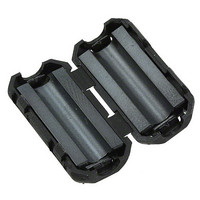
FERRITE EMI SPLIT/SNAP-ON CORE
Manufacturer
Laird Technologies
Series
28Ar
Type
Core-Splitr
Datasheet
1.28A2005-0A2.pdf
(28 pages)
Specifications of 28A2005-0A2
Filter Type
Round Cable, Snap On
Shape
Cylindrical
Frequency
100MHz
Impedance
190 Ohm
Package / Case
13.00mm O.D. x 5.00mm I.D. x 25.50mm L
Test Frequency
100 MHz
Product
Clamp-On Ferrite Suppressors
Termination Style
Cable Snap
Diameter, Cable
0.098 "
Impedance, At 100 Mhz
190 Ohms
Impedance, At 25 Mhz
88 Ohms
Impedance, At 300 Mhz
330 Ohms
Material, Core
28
Special Features
Black Plastic Snap-On Case
Termination
Cable
Dimensions
13 mm Dia. x 25.5 mm L
Lead Free Status / RoHS Status
Lead free / RoHS Compliant
Lead Free Status / RoHS Status
Lead free / RoHS Compliant, Lead free / RoHS Compliant
Other names
240-2600


4
www.lairdtech.com
FERRITE MATERIAL
LF, 28 & HF MATERIAL IMPEDANCE VS FREQUENCY (300 KHz - 2 GHz)
Impedance Materials for Cable & Wiring Harness Cores
DESIGN & SELECTION
SELECT THE APPROPRIATE FERRITE MATERIAL
For the EMI frequency range to be attenuated, refer to cable core material impedance vs.frequency chart above.
FERRITE MATERIAL COMPOSITION AFFECTS CORE PERFORMANCE MOST
High-performance material is best. Cheap, low-performance materials require the use of larger, heavier cores.
SHAPE (DESIGN) AND MASS OF THE FERRITE CORE SIGNIFICANTLY AFFECT IMPEDANCE
DON’T OVER SIZE
Use high-performance ferrite material and select the smallest core that will do the job. High-performance material
allows the use of smaller, lighter and lower cost cores.
SELECT A FERRITE CORE THAT FITS OVER THE CABLE’S OUTSIDE DIMENSIONS
Core should slide easily over the cable during installation.
WHEN POSSIBLE, INSTALL A CABLE CORE OVER WIRES IN A COMMON MODE CONFIGURATION
(Out and back lines inside the same ferrite cable core). A differential cable pair inside the same core will make the ferrite core a
common mode choke that is not susceptible to saturation from very high currents.
INSTALL THE FERRITE CORE NEAR THE NOISE SOURCE
ADDITIONAL TURNS THROUGH A CORE WILL PROVIDE MULTIPLE AMOUNTS OF PEAK IMPEDANCE
Example: Two wire turns provide four times the impedance of one turn (pass through) the ferrite core. Also, with each added turn,
the peak impedance shifts to a slightly lower frequency.
TWO-PIECE SPLIT CORES ARE AVAILABLE
One-piece cylindrical or flat ribbon ferrite core shapes are usually preferable, but split cores can be used in applications where
cores cannot slide over cable ends and connectors. Some split cores are available with snap-on plastic cases or metal clips.
SIDE-BY-SIDE IMPEDANCE TESTING OF FERRITE CORES IS THE BEST WAY TO COMPARE
PERFORMANCE OF DIFFERENT CORES
Ferrite core impedance measurement equipment and test methods are not standardized in the industry.
Every ferrite company has their own test methods. Catalog (web site) impedance data cannot be accurately compared.
Optimized, high-performance, low-cost custom part designs are available.
FERRITE EMI CABLE CORES
0.3
0.5
LF Low Frequency
28 Broadband High Performance
HF High Frequency
500
1
LF
5
10
Frequency (MHz)
50
100
“RULES OF THUMB”
COMPARISON
28
HF
1000
2000
Related parts for 28A2005-0A2
Image
Part Number
Description
Manufacturer
Datasheet
Request
R

Part Number:
Description:
Bluetooth Serial Module Development Kit
Manufacturer:
Laird Technologies
Part Number:
Description:
BLUETOOTH MODULE DEVELOPMENT KIT
Manufacturer:
Laird Technologies
Part Number:
Description:
Bluetooth 2.0 AT Data Module, Internal Antenna Development Kit
Manufacturer:
Laird Technologies

Part Number:
Description:
BLUETOOTH EVAL BOARD BTM511
Manufacturer:
Laird Technologies
Datasheet:

Part Number:
Description:
Bluetooth / 802.15.1 Modules & Development Tools BLUETTH Multimed MODLE, No ANT DEVKIT
Manufacturer:
Laird Technologies
Datasheet:

Part Number:
Description:
DEV KIT PRM122
Manufacturer:
Laird Technologies
Datasheet:
Part Number:
Description:
DEV KIT PRM123
Manufacturer:
Laird Technologies
Datasheet:

Part Number:
Description:
KIT FOR PRM112
Manufacturer:
Laird Technologies
Datasheet:
Part Number:
Description:
DEV KIT PRM121
Manufacturer:
Laird Technologies
Datasheet:

Part Number:
Description:
KIT DEVELOPMENT FOR LT2510 U.FL
Manufacturer:
Laird Technologies
Datasheet:

Part Number:
Description:
CHOKE COMMON MODE 110 OHMS SMD
Manufacturer:
Laird Technologies
Datasheet: