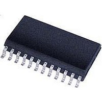
MTS62C19A-HS105 Microchip Technology, MTS62C19A-HS105 Datasheet - Page 9

MTS62C19A-HS105
Manufacturer Part Number
MTS62C19A-HS105
Description
Dual Full-Bridge PWM Motor Driver 24 SOIC .300in TUBE
Manufacturer
Microchip Technology
Type
Dual Full-Bridge Motor Driverr
Datasheet
1.MTS62C19A-HS105.pdf
(18 pages)
Specifications of MTS62C19A-HS105
Product
Stepper Motor Controllers / Drivers
Operating Supply Voltage
10 V to 40 V
Supply Current
0.8 mA
Mounting Style
SMD/SMT
Package / Case
SOIC-24
Operating Temperature
- 20 C to + 85 C
Peak Reflow Compatible (260 C)
Yes
Rohs Compliant
Yes
Motor Type
Full Bridge
No. Of Outputs
2
Output Current
1A
Supply Voltage Range
10V To 40V
Driver Case Style
SOIC
No. Of Pins
24
Operating Temperature Range
-20°C To +85°C
Lead Free Status / RoHS Status
Lead free / RoHS Compliant
Lead Free Status / RoHS Status
Lead free / RoHS Compliant
Other names
MTS62C19A-HS105TR
Available stocks
Company
Part Number
Manufacturer
Quantity
Price
Company:
Part Number:
MTS62C19A-HS105
Manufacturer:
MICROCHIP
Quantity:
12 000
3.2
The current level in each motor winding is controlled by
a PWM circuit with a fixed T
flowing in the winding is sensed through an external
sensing resistor Rs connected between the power
bridge's source pin SENSE (sources of transistors Na
and Nb) and GND.
FIGURE 3-2:
The voltage across Rs is compared to a fraction of the
reference voltage VREF, chosen with the logic input
bits I0 and I1
the load current can also be switched off completely
when both logic inputs are high. Note that any logic
input left unconnected will be treated as a high level
(pull-up resistor).
The maximum trip current for regulation, given for I0 I1
= 00 is calculated in
TABLE 3-3:
When the maximum allowed current is reached, the
bridge source is turned off during a fixed period T
(typically 50us) given by a non-retriggerable pulse gen-
erator and the external timing components Rt (20k-
100 k range) and Ct (100 pF-1000 pF range):
toff = 1.1*(Rt*Ct)
During T
driver is re-enabled, the winding current increases
again until it reaches the threshold, and the cycle
repeats itself maintaining the load current at the desired
level.
2010 Microchip Technology Inc.
OFF
PWM Current Control
I0
0
1
0
1
the winding current decreases. When the
(Table
VREF
CURRENT LEVEL CONTROL TRUTH TABLE
I0
I1
Equation
3-3). The power bridge and thus
PWM Current Control Circuit Principle (Channel 1 Shown)
OFF
3-1.
time. The load current
COMPIN
Cc
I1
0
0
1
1
÷10
Rc
OFF
RC
Ct
One-Shot
Comp. Trip Voltage
Vtrip = 1/10*Vref
Vtrip = 1/15*Vref
Vtrip = 1/30*Vref
EQUATION 3-1:
Rt
Source
Disable
Power
Bridge
x
Pa
Na
VLOAD
I
MAX
SENSE
Rs
MTS62C19A
Pb
Nb
10
2/3*Imax = Vref/15RS
1/3*Imax = Vref/30RS
V
Imax = Vref/10RS
REF
*
Output Current
0 (no current)
R
OUTA
OUTB
S
DS22260A-page 9


