MCP73871-3CCI/ML Microchip Technology, MCP73871-3CCI/ML Datasheet - Page 24

MCP73871-3CCI/ML
Manufacturer Part Number
MCP73871-3CCI/ML
Description
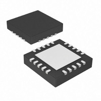
USB/AC Battery Charger With Power Path Management 20 QFN 4x4mm TUBE
Manufacturer
Microchip Technology
Specifications of MCP73871-3CCI/ML
Function
Charge Management
Battery Type
Lithium-Ion (Li-Ion), Lithium-Polymer (Li-Pol)
Voltage - Supply
4.4 V ~ 6 V
Operating Temperature
-40°C ~ 85°C
Mounting Type
Surface Mount
Package / Case
20-VFQFN Exposed Pad
Product
Charge Management
Output Voltage
4.35 V
Output Current
50 mA to 1000 mA
Operating Supply Voltage
4.65 V to 6 V
Maximum Operating Temperature
+ 85 C
Minimum Operating Temperature
- 40 C
Mounting Style
SMD/SMT
Lead Free Status / RoHS Status
Lead free / RoHS Compliant
For Use With
MCP73871DM-VPCC - DEMO BOARD FOR MCP73871MCP73871EV - EVALUATION BOARD FOR MCP73871
Lead Free Status / Rohs Status
Lead free / RoHS Compliant
MCP73871
For example, by utilizing a 10 kΩ at 25°C NTC
thermistor with a sensitivity index, β, of 3892, the
charge temperature range can be set to 0°C - 50°C by
placing a 1.54 kΩ resistor in series (R
69.8 kΩ resistor in parallel (R
6.1.1.6
A status output provides information on the state of
charge. The output can be used to illuminate external
LEDs or interface to a host microcontroller. Refer to
Table 5-1
output during a charge cycle.
6.1.1.7
The preferred discharge current for Lithium-Ion cells
should always follow references and guidance from
battery manufacturers. Due to the safety concerns
when using Lithium-Ion batteries and power dissipa-
tion of linear solutions, the system load when design
with the MCP73871 device is recommended to be less
than 1A or the maximum discharge rate of the
selected Lithium-Ion cell. Whichever is smaller is
recommended.
The idea diode between V
drive a maximum current up to 2A. The built-in thermal
shutdown protection may turn the MCP73871 device
off with high current.
DS22090A-page 24
for a summary of the state of the status
Charge Status Interface
System Load Current
BAT
T2
and OUT is designed to
) with the thermistor.
T1
), and a
6.2
For optimum voltage regulation, place the battery pack
as close as possible to the device’s V
recommended to minimize voltage drops along the
high current-carrying PCB traces.
If the PCB layout is used as a heatsink, adding many
vias in the heatsink pad can help conduct more heat to
the backplane of the PCB, thus reducing the maximum
junction temperature.
PCB Layout Issues
© 2008 Microchip Technology Inc.
BAT
and V
SS
pins,


