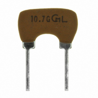
CDALF10M7GA042-B0 Murata Electronics North America, CDALF10M7GA042-B0 Datasheet

CDALF10M7GA042-B0
Specifications of CDALF10M7GA042-B0
Related parts for CDALF10M7GA042-B0
CDALF10M7GA042-B0 Summary of contents
Page 1
... Temperature Range 株式会社 村 田 製 作 所 納 入 仕 様 書 CDALF10M7GA042-B0 承 認 Approved by 貴 社 部 品 番 号 Customer's Part Number ...
Page 2
Drawing No. JGM40-2533A 電気的性能 Electrical Characteristics 4. 項 目 Item 中心周波数 (fo) 4-1 Center Frequency (fo) 復調出力電圧 (foにて) 4-2 Recovered Audio Voltage (at fo) 復調歪率 (foにて) 4-3 Distortion (at fo) 復調3dB帯域幅 4-4 Recovered Audio 3dB Bandwidth 温度特性 4-5 -10°C ~ ...
Page 3
Drawing No. JGM40-2533A 測定方法 Measuring Method 5. 入力信号条件 5-1-1 Input Signal 中心周波数 (fo) 5-1-2 Center Frequency (fo) Center frequency is defined as the frequency at that D.C. 復調出力電圧 5-1-3 Recovered Audio Voltage 復調歪率 5-1-4 Distortion 復調3dB帯域幅 5-1-5 Recovered Audio ...
Page 4
... Drawing No. JGM40-2533A 5-3 測定回路 Measuring Circuit 0.01μ Ceramic Discriminator : CDALF10M7GA042-B0 株式会社 村 田 製 作 所 IF-in 0.01μ 0.1μ 0.1μ SA605 ...
Page 5
Drawing No. JGM40-2533A 外形寸法図 Dimensions 6. W 0.4±0.1 0.65±0.1 0.5±0.1 5.0±0.2 推奨基板穴 Recommended PCB hole 幅 Width 厚み Thickness 高さ Height 端子長さ Length of Terminal 表示 Marking : 10.7G :社標 Vender's Code * :製造年月度 EIAJ Monthly Code 単位 Unit ...
Page 6
Drawing No. JGM40-2533A 機械的性能 Physical Characteristics 7. 項 目 Item 端子強度 7-1 Terminal Strength 引張強度 各端子の軸方向に4.9Nの静荷重を10 ~ 15秒 間加える。 Terminal Pulling Force of 4.9N is applied to each lead in axial direction for seconds. 屈曲強度 各端子の軸方向に2.45Nの静荷重を加え、端子 を90°曲げ元に戻し、さらに逆方向に90°折り ...
Page 7
Drawing No. JGM40-2533A 耐候性能 Environmental Characteristics 8. 項 目 Item 温度+60±2°C湿度90 + 耐湿特性 8-1 にて100時間保持した後、常温に取り出して1 時間後に測定する。 Components shall be left in a chamber (90 to Damp Heat 95% R.H. at +60±2°C) for 100 hours, then (Storage) measured after leaving in ...
Page 8
Drawing No. JGM40-2533A 中心周波数の変化 Center Frequency Drift 復調出力電圧の変化 Recovered Audio Voltage Drift 注意 : 各変化量は試験前の初期値を基準とします。 Note : The limits in the above table refer to 包装規格 Packaging Standard 9. 最小包装単位 (製品500個) 毎に包装し、品番・数量及びロット番号を表示します。 Each minimum package unit of components (500pcs) ...
Page 9
Drawing No. JGM40-2533A ! 注意 Cautions 10. 10-1 用途の限定 Limitation of Applications 当製品について、その故障や誤動作が人命または財産に危害を及ぼす恐れがある等の理由に より、高信頼性が要求される以下の用途でのご使用をご検討の場合は、必ず事前に当社まで ご連絡下さい。 ①航空機器 ②宇宙機器 ③海底機器 ④発電所制御機器 ⑤医療機器 ⑥輸送機器(自動車、列車、船舶等) ⑦交通用信号機器 ⑧防災/防犯機器 ⑨情報処理機器 ⑩その他上記機器と同等の機器 Please contact us before using our products for the applications listed below which require especially high reliability for the prevention of defects which ...
Page 10
Drawing No. JGM40-2533A . 使用上の注意 Caution for Use 11 11-1 当製品の端子を折り曲げて使用しないで下さい。また、基板に実装された状態で過度の力が 加わると不具合を生じる事が有りますので取り扱いには充分ご注意下さい。 Do not use this component with bend. The component may be damaged if excess mechanical stress is applied to it mounted on the printed circuit board. 11-2 規格以上の衝撃が印加された場合、不具合が生じる事があります。取り扱いには充分ご注意 ...
Page 11
... Please do not drop the products to avoid cracking of ceramic element. 株式会社 村 田 製 作 所 ...
Page 12
Drawing No. JGM40-2533A ! お願い Note 13. 13-1 ご使用に際しましては、貴社製品に実装された状態で必ず評価して下さい。 Please make sure that your product has been evaluated In view of your specifications with our product being mounted to your product. 13-2 当製品を当納入仕様書の記載内容を逸脱して使用しないで下さい。 You are requested not to use our ...


