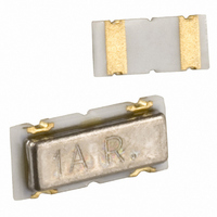
CDSCB10M7GA135S-R0 Murata Electronics North America, CDSCB10M7GA135S-R0 Datasheet

CDSCB10M7GA135S-R0
Specifications of CDSCB10M7GA135S-R0
Related parts for CDSCB10M7GA135S-R0
CDSCB10M7GA135S-R0 Summary of contents
Page 1
... Temperature Range 株式会社 村 田 製 作 所 納 入 仕 様 書 CDSCB10M7GA135S-R0 承 認 Approved by 貴 社 部 品 番 号 Customer's Part Number Murata Manufacturing Co.,Ltd. ...
Page 2
Drawing No. JGM40-2671A 電気的性能 Electrical Characteristics 4. 項 目 Item 中心周波数 (fo) 4-1 Center Frequency (fo) 復調出力電圧 (foにて) 4-2 Recovered Audio Output Voltage (at fo) 復調3dB帯域幅 4-3 Recovered Audio 3dB Bandwidth 温度特性 4-4 -40°C ~ +85°Cの範囲内での 中心周波数 (fo) 変化 Temperature ...
Page 3
Drawing No. JGM40-2671A 測定方法 Measuring Method 5. 入力信号条件 5-1-1 Input Signal 中心周波数 (fo) 5-1-2 Center Frequency (fo) Center frequency is defined as the frequency where 復調出力電圧 5-1-3 Recovered Audio Output Voltage 復調3dB帯域幅 5-1-4 Recovered Audio 3dB Bandwidth 5-2 測定条件 ...
Page 4
... TH71112(Melexis) Applied IC:TH71101,TH71102,TH71111 or TH71112(Melexis) Ceramic Discriminator:CDSCB10M7GA135S-R0 株式会社 村 田 製 作 所 FSK-OUT 0.1μ 0.01μ 1000p 330k 23 ...
Page 5
Drawing No. JGM40-2671A 外形寸法図 Dimensions 6. 4.5±0 0.2±0.2 4.1max. 0.4(ref.) 0.8±0.1 1.5±0.1 (推奨ランド寸法) (Recommended Land Pattern) 3.0 1.0 2.0 株式会社 村 田 製 作 所 0.4±0.05 0.4(ref.) 0.8±0.1 1.5±0.1 1 * EIAJ Monthly Code ** 単位 Unit :mm ...
Page 6
Drawing No. JGM40-2671A 機械的性能 Physical Characteristics 7. 項 目 Item 基板たわみ強度 下図に示す様に加圧し、1回1秒の割合で5回加 7-1 圧する。プリント基板は第1図を使用します。 After components soldered on PCB specified in Bend Strength PCB Fig. 1, the load shall be applied to the PCB as shown in below figure for ...
Page 7
Drawing No. JGM40-2671A 耐候性能 Environmental Characteristics 8. 項 目 Item 温度+85±2°C湿度85 + 耐湿特性 8-1 て1000時間保持した後、常温に取り出して1時 間後に測定する。 Components shall be left in a chamber (85 to Damp Heat 90% R.H. at +85±2°C) for 1000 hours, then (Storage) measured after leaving ...
Page 8
Drawing No. JGM40-2671A 項 目 Item 高温放置 温度+85±2°Cの恒温槽中に1000時間保持し、常 8-3 温に取出して、1時間後に測定する。 Dry Heat Components shall be left in a chamber (Storage) (Temperature: +85±2°C) for 1000 hours, then measured after leaving in natural condition for 1 hour. 低温放置 温度-55±2°Cの恒温槽中に1000時間保持し、常 8-4 温に取出して、1時間後に測定する。 ...
Page 9
Drawing No. JGM40-2671A 第1図 7-1項及び8-2項 (はんだ耐熱性) 信頼性試験用プリント基板 Fig. 1 PCB for Item 7-1 and 8-2 (Resistance to Soldering Heat) Environmental Test ø4.5 指定なき公差:±0.1mm Tolerance unless otherwise specified * プリント基板材質 : ガラスエポキシ (t=0.8mm) PCB Material 株式会社 村 田 製 作 所 100 50 ...
Page 10
Drawing No. JGM40-2671A プラスチックテ-プ収納方法 Taping Method of Plastic Package 9. 9-1 プラスチックテ-プ外形寸法図 Dimensions of Carrier Tape 4.0±0.1 (0.1to 0.7N) 引きはがし強度 引きはがし強度 Peel strength Peel strength 10°max. ・カバーテープ側に品番表示がきます。 Part Number marked side is always facing upside. 株式会社 村 田 製 作 所 +0.1 ø1.5-0 2.0±0.05 ...
Page 11
Drawing No. JGM40-2671A 9-2 リール外形寸法図 Dimension of Reel 9-3 テーピング方法 Taping Method 9-3-1 テープは右巻き(テープの端を手前に取り出した時、送り穴が右側になる)とします。 The carrier tape shall be wound clockwise. The feeding holes shall be to the right side as the tape is pulled toward the user. ...
Page 12
Drawing No. JGM40-2671A 9-3-5 チップの向きは、裏表の反転のなきこととします。 The direction of components shall be fixed. 9-3-6 チップは端数を除いて1リール2,000個収納とします。 A reel shall contain 2,000pcs of components. 9-3-7 リール側面に表示ラベルを貼り、当社品番・貴社部品番号・数量及び、検査番号を記入しま す。 Part Number, Customer's Part Number, quantity and Outgoing Inspection Number shall be printed on the ...
Page 13
Drawing No. JGM40-2671A ! 注意 Cautions 10. 10-1 用途の限定 Limitation of Applications 当製品について、その故障や誤動作が人命または財産に危害を及ぼす恐れがある等の理由に より、高信頼性が要求される以下の用途でのご使用をご検討の場合は、必ず事前に当社まで ご連絡下さい。 ①航空機器 ②宇宙機器 ③海底機器 ④発電所制御機器 ⑤医療機器 ⑥輸送機器(自動車、列車、船舶等) ⑦交通用信号機器 ⑧防災/防犯機器 ⑨情報処理機器 ⑩その他上記機器と同等の機器 Please contact us before using our products for the applications listed below which require especially high reliability for the prevention of defects which ...
Page 14
Drawing No. JGM40-2671A . 使用上の注意 Caution for Use 11 11-1 基板に実装された状態で過度の力が加わると不具合を生じる事が有りますので取り扱いには 充分ご注意下さい。 The component may be damaged if excess mechanical stress is applied to it mounted on the printed circuit board. 11-2 基板設計の際には、基板のそり・たわみに対して極力ストレスが加わらない様な部品配置に して下さい。 Design layout of components on the ...
Page 15
Drawing No. JGM40-2671A 11-5 当製品は、画像認識タイプの位置決め機構実装機に対応しています。但し、実装条件によっ ては過大な衝撃が加わり製品本体を破損する場合がありますので事前に使用される実装機で 必ず評価確認をして下さい。なお、メカチャック機構タイプの実装機での実装は避けて下さ い。詳細については事前に当社までお問い合わせ下さい。 The component is recommended with placement machines with employ optical placement capabilities. The component might be resulted in damage by excessive mechanical force. Please make sure that you have evaluated by ...
Page 16
... Please do not drop the products to avoid cracking of ceramic element. 株式会社 村 田 製 作 所 ...
Page 17
Drawing No. JGM40-2671A ! お願い Note 13. 13-1 ご使用に際しましては、貴社製品に実装された状態で必ず評価して下さい。 Please make sure that your product has been evaluated In view of your specifications with our product being mounted to your product. 13-2 当製品を当納入仕様書の記載内容を逸脱して使用しないで下さい。 You are requested not to use our ...


