B82721K2401N021 EPCOS Inc, B82721K2401N021 Datasheet - Page 4
B82721K2401N021
Manufacturer Part Number
B82721K2401N021
Description
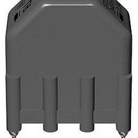
Power Inductors
Manufacturer
EPCOS Inc
Series
B82721A/J/Kr
Datasheet
1.B82721A2152N1.pdf
(8 pages)
Specifications of B82721K2401N021
Inductance
300 uH
Tolerance
30 %
Maximum Dc Current
0.4 Amp
Maximum Dc Resistance
1700 mOhms
Dimensions
13.2 mm W x 18.2 mm L x 20.3 mm H
Shielding
Unshielded
Termination Style
Through Hole
Package / Case
18.2 mm x 13.2 mm x 20.3 mm
Lead Free Status / RoHS Status
Lead free / RoHS Compliant


Technical data and measuring conditions
Rated voltage V
Test voltage V
Rated temperature T
Rated current I
Rated inductance L
Inductance tolerance
Inductance decrease L/L
Stray inductance L
DC resistance R
Solderability (lead-free)
Resistance to soldering heat
(wave soldering)
Climatic category
Storage conditions (packaged)
Weight
Approvals
Please read Cautions and warnings and
Important notes at the end of this document.
Power line chokes
Current-compensated ring core double chokes
test
R
R
typ
stray,typ
R
R
0
250 V AC (50/60 Hz)
1500 V AC, 2 s (line/line)
40 °C / 50 °C / 60 °C
Referred to 50 Hz and rated temperature
Measured with Agilent 4284A at 0.1 mA, 20 °C
Measuring frequency: L
Inductance is specified per winding.
< 10% at DC magnetic bias with I
Measured with Agilent 4284A at 5 mA, 20 °C, typical values
Measuring frequency: L
Measured at 20 °C, typical values, specified per winding
Sn96.5Ag3.0Cu0.5: (245 5) °C, (3 0.3) s
Wetting of soldering area
(to IEC 60068-2-20, test Ta)
(260 5) °C, (10 1) s
(to IEC 60068-2-20, test Tb)
40/125/56 (to IEC 60068-1)
–25 °C … +40 °C,
Approx. 5 g
EN 60938-2, UL 1283
30% at 20 °C
4
10/08
75% RH
L
L
R
R
R
R
> 1 mH = 10 kHz
> 1 mH = 10 kHz
1 mH = 100 kHz
1 mH = 100 kHz
95%
R
, 20 °C
B82721A/J/K
Related parts for B82721K2401N021
Image
Part Number
Description
Manufacturer
Datasheet
Request
R

Part Number:
Description:
Ind Current Compensated Choke 1mH 30% Ferrite 2A Pin
Manufacturer:
EPCOS (TDK)
Part Number:
Description:
Power Line Chokes
Manufacturer:
EPCOS AG
Datasheet:
Part Number:
Description:
Chokes for Power Lines Current-Compensated Ring Core Double Chokes
Manufacturer:
EPCOS [EPCOS]
Datasheet:


Part Number:
Description:
CAP .15UF 63V METAL POLY
Manufacturer:
EPCOS Inc
Datasheet:

