SRR1003-121M Bourns Inc., SRR1003-121M Datasheet
SRR1003-121M
Manufacturer Part Number
SRR1003-121M
Description
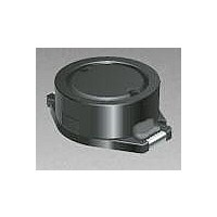
Power Inductors 120uH 20%
Manufacturer
Bourns Inc.
Series
SRR1003r
Datasheet
1.SRR1003-100M.pdf
(2 pages)
Specifications of SRR1003-121M
Inductance
120 uH
Tolerance
20 %
Maximum Dc Current
0.35 Amp
Maximum Dc Resistance
1.52 Ohms
Dimensions
10.3 mm W x 12.7 mm L x 3 mm H
Termination Style
SMD/SMT
Lead Free Status / RoHS Status
Lead free / RoHS Compliant


Bourns Part No.
SRR1003-1R8M
SRR1003-2R2M
SRR1003-3R0M
SRR1003-3R9M
SRR1003-4R7M
SRR1003-7R5M
SRR1003-100M
SRR1003-120M
SRR1003-150M
SRR1003-180M
SRR1003-220M
SRR1003-270M
SRR1003-330M
SRR1003-390M
SRR1003-470M
SRR1003-560M
SRR1003-680M
SRR1003-820M
SRR1003-101M
SRR1003-121M
SRR1003-151M
SRR1003-181M
SRR1003-221M
SRR1003-271Y
SRR1003-331Y
SRR1003-391Y
SRR1003-471Y
Electrical Specifications
Soldering Profile
300
250
200
150
100
50
0
0
<1> Max. of 10 seconds at 250 °C
<2> Max. of 30 seconds > 220 °C
Ramp-up
4 °/second maximum
Inductance 1kHz
50
(µH)
100
120
150
180
220
270
330
390
470
1.8
2.2
3.0
3.9
4.7
7.5
10
12
15
18
22
27
33
39
47
56
68
82
120 - 150 seconds
Tol. %
± 20
± 20
± 20
± 20
± 20
± 20
± 20
± 20
± 20
± 20
± 20
± 20
± 20
± 20
± 20
± 20
± 20
± 20
± 20
± 20
± 20
± 20
± 20
± 15
± 15
± 15
± 15
100
Ref.
10
11
11
10
10
10
18
20
20
20
17
17
17
18
18
15
15
20
23
22
23
20
20
26
26
28
28
Q
Time (seconds)
Frequency
0.796M
0.796M
0.796M
0.796M
0.796M
0.796M
0.796M
0.796M
0.796M
7.96M
7.96M
7.96M
7.96M
7.96M
7.96M
2.52M
2.52M
2.52M
2.52M
2.52M
2.52M
2.52M
2.52M
2.52M
2.52M
2.52M
2.52M
(MHz)
Test
150
Features
SRR1003 Series - Shielded Power Inductors
<1>
Available in E6 series
Low profile of 3 mm
High current
Lead free
RoHS compliant*
<2>
100.0
(MHz)
Min.
90.0
70.0
60.0
50.0
32.0
28.0
26.0
25.0
14.0
22.0
19.0
17.0
16.0
14.0
13.0
11.0
11.0
10.0
SRF
9.0
8.0
7.0
6.0
4.1
3.6
2.6
2.1
200
Ramp-down
5 °C/second maximum
0.045
0.062
RDC
0.03
0.07
0.08
0.10
0.15
0.19
0.20
0.27
0.30
0.40
0.45
0.56
0.65
0.68
0.80
1.20
1.40
1.52
1.80
2.20
2.20
3.10
3.60
4.60
5.10
(Ω Ω )
250 °C
I rms
Max.
3.00
2.76
2.20
2.10
1.90
1.44
1.24
1.10
1.02
0.90
0.85
0.75
0.70
0.65
0.60
0.52
0.48
0.42
0.40
0.35
0.32
0.28
0.26
0.22
0.20
0.18
0.16
250
(A)
Customers should verify actual device performance in their specific applications.
I sat
8.00
6.70
5.60
5.20
4.60
3.90
3.30
3.00
2.60
2.50
2.10
1.90
1.70
1.60
1.40
1.30
1.20
1.00
0.95
0.85
0.80
0.75
0.65
0.60
0.55
0.46
0.45
Typ.
(A)
300
*RoHS Directive 2002/95/EC Jan 27 2003 including Annex
Applications
Test Voltage........................................1 V
Reflow soldering.....250 °C; 10 sec max.
Operating Temperature .-40 °C to +125 °C
Storage Temperature..-40 °C to +125 °C
Resistance to Soldering Heat
Core.....................Ferrite DR and RI core
Wire .............................Enameled copper
Base ......................................LCP E4008
Terminal ....................................Cu/Ni/Sn
Rated Current
Temperature Rise
Packaging...................1000 pcs. per reel
General Specifications
Materials
Product Dimensions
Recommended Layout
....................Ind. drop 10 % typ. at Isat
............................250 °C, 10 sec. max.
......................40 °C max. at rated Irms
Input/output of DC/DC converters
Power supplies for:
•
•
•
•
Specifications are subject to change without notice.
Portable communication equipment
Camcorders
LCD TVs
Car radios
(.287)
7.3
DIMENSIONS:
(.500 ± .004)
(In compliance with JEDEC,
12.7 ± 0.1
(Temperature rise included)
(.299)
TYP.
7.6
(.118)
3.0
J-STD-020C, Table 4-2)
(INCHES)
(.110)
2.8
MM
(.098)
TYP.
(.118)
2.5
3.0
(.098)
(.406 ± .008)
TYP.
2.5
10.3 ± 0.2
MAX.
Related parts for SRR1003-121M
Image
Part Number
Description
Manufacturer
Datasheet
Request
R

Part Number:
Description:
Power Inductors 7.5uH 20%
Manufacturer:
Bourns Inc.
Datasheet:
Part Number:
Description:
Power Inductors 47uH 20%
Manufacturer:
Bourns Inc.
Datasheet:
Part Number:
Description:
Power Inductors 3uH 20%
Manufacturer:
Bourns Inc.
Datasheet:
Part Number:
Description:
Power Inductors 18uH 20%
Manufacturer:
Bourns Inc.
Datasheet:
Part Number:
Description:
Power Inductors 18uH 20%
Manufacturer:
Bourns Inc.
Datasheet:
Part Number:
Description:
Power Inductors 15uH 20%
Manufacturer:
Bourns Inc.
Datasheet:

Part Number:
Description:
POWER INDUCTOR, 10UH 3.3A 20% 28MHZ
Manufacturer:
Bourns Inc.
Datasheet:
Part Number:
Description:
POWER INDUCTOR 2.2UH 6.7A 20% 90MHZ
Manufacturer:
Bourns Inc.
Datasheet:
Part Number:
Description:
POWER INDUCTOR 4.7UH 4.6A 20% 50MHZ
Manufacturer:
Bourns Inc.
Datasheet:

Part Number:
Description:
Manufacturer:
Bourns, Inc.
Datasheet:
Part Number:
Description:
11mm Potentiometer
Manufacturer:
Bourns, Inc.
Datasheet:
Part Number:
Description:
Manufacturer:
Bourns, Inc.
Datasheet:
SRR1003-121M Summary of contents
Page 1
... SRR1003-270M 27 ± SRR1003-330M 33 ± SRR1003-390M 39 ± SRR1003-470M 47 ± SRR1003-560M 56 ± SRR1003-680M 68 ± SRR1003-820M 82 ± SRR1003-101M 100 ± SRR1003-121M 120 ± SRR1003-151M 150 ± SRR1003-181M 180 ± SRR1003-221M 220 ± SRR1003-271Y 270 ± SRR1003-331Y 330 ± SRR1003-391Y 390 ± SRR1003-471Y 470 ± ...
Page 2
... SRR1003 Series - Shielded Power Inductors Packaging Specifications 330 2.0 ± 0.5 DIA. (12.99) (.079 ± .020) 21.0 ± 0.8 (.827 ± .031) 13.0 ± 0.5 DIA. (.512 ± .020) END 24 (.945) 3.1 (.122) NO COMPONENT REV. 02/06 Specifications are subject to change without notice. ...