535512-2 TE Connectivity, 535512-2 Datasheet - Page 204
535512-2
Manufacturer Part Number
535512-2
Description
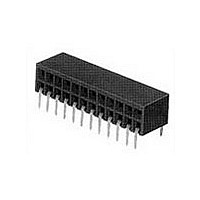
Conn Socket Strip RCP 20 POS 2.54mm Solder RA Thru-Hole Gang of Tubes
Manufacturer
TE Connectivity
Type
Socket Stripr
Specifications of 535512-2
Pitch
2.54 mm
Number Of Rows
2
Number Of Contacts
20
Gender
RCP
Contact Plating
Gold Over Nickel
Termination Method
Solder
Pitch (mm)
2.54mm
Number Of Contact Rows
2
Mounting Style
Through Hole
Body Orientation
Right Angle
Operating Temp Range
-55C to 125C
Current Rating (max)
2/ContactA
Contact Material
Phosphor Bronze
Contact Resistance Max
12mOhm
Housing Material
Polychlorinated Terp
Housing Color
Black
Product Height (mm)
6.05mm
Product Length (mm)
25.4mm
Product Depth (mm)
8.13mm
Rohs Compliant
NO
Product Type
Connector
Connector Series
Mod II
Profile
Standard
Mounting Pattern (mm [in])
2.54 x 7.87 [.100 x .310]
Sealed
No
Holddown Feature
Without
Pcb Mounting Orientation
Right Angle
Pcb Mount Retention
Without
Termination Method To Pc Board
Through Hole - Solder
Closed Entry
With
Board Standoff
With
Stackable
Yes
Contact - Rated Current (a)
2
Contact Resistance (m?)
12
Insulation Resistance (m?)
5,000
Dielectric Withstanding Voltage (v)
750
Termination Post Length (mm [in])
2.92 [0.115]
Solder Tail Contact Plating
Tin-Lead over Nickel
Connector Height (mm [in])
6.05 [0.238]
Number Of Positions
20
Centerline, Matrix (mm [in])
2.54 x 2.54 [.100 x .100]
Contact Plating, Mating Area, Material
Gold (30)
Contact Base Material
Phosphor Bronze
Contact Configuration
Short Point
Housing Entry Style
Side
Ul Flammability Rating
UL 94V-0
Government/industry Qualification
No
Rohs/elv Compliance
Not ELV/RoHS compliant
Lead Free Solder Processes
Reflow solder capable to 245°C, Reflow solder capable to 260°C
Approved Standards
UL E28476, CSA LR7189
Operating Temperature (°c)
-55 – +125
High Temperature Compatible
Yes
Packaging Quantity
100
Packaging Method
Gang of Tubes
Lead Free Status / RoHS Status
Not Compliant
Available stocks
Company
Part Number
Manufacturer
Quantity
Price
Company:

Part Number:
535512-2
Manufacturer:
TE Connectivity AMP Connectors
Quantity:
106


5
204
Material
Black polyester
Technical Documents
The barrier insert can be
used on double row headers
(.100 x .100 [2.54 x 2.54]
centers), including shrouded
versions—3 and 4 sides,
as well as unshrouded
straight post headers. With
one barrier insert several
configurations can be
obtained, providing headers
with capabilities of accept-
ing various combinations of
polarized and non-polarized
AMPMODU connectors.
For unshrouded headers,
the barrier insert is used
to establish polarization
and to compartmentalize
the header. For shrouded
headers, the barrier insert is
used to compartmentalize
the header, while maintaining
polarization. The barrier
insert itself is notched to
facilitate cutting off the
ends with a simple tool
such as tin snips or scissors
to achieve the desired
configuration.
Catalog 1307819
Revised 8-08
www.tycoelectronics.com
— page 276
are metric equivalents.
Dimensions are in inches and
millimeters unless otherwise
specified. Values in brackets
AMPMODU Interconnection System
Accessories: Barrier Insert, Part No. 87743-1
Barrier Insert Cutoffs
Typical Barrier Insert Applications
For Unshrouded Double-Row, Straight Post Headers,
.100 x .100 [2.54 x 2.54] Centers
Note: All configurations of barrier inserts compartmentalize headers and maintain polarization,
For Shrouded Double-Row, 3 and 4 Sided Headers,
.100 x .100 [2.54 x 2.54] Centers
Note: Right-angle (Figs. 2 and 3) and “T” (Fig. 1) configurations of barrier insert establish
Note: All part numbers are RoHS compliant.
[7.98]
.314
(Left and Right Sides)
[0.94]
.037
Partial Cutoff
except bar (Fig. 4) configuration, which is used primarily for compartmentalizing headers.
polarization; bar (Fig. 4) configuration of barrier insert compartmentalizes header.
Fig. 1
See Fig. 2
See Fig. 3
[11.33]
Dimensions are shown for
reference purposes only.
Specifications subject
to change.
.446
[3.23]
.127
Complete Cutoff
Partial Cutoff
(Right Side)
(Left Side)
Fig. 2
See Fig. 4
See Fig. 4
USA: 1-800-522-6752
Canada: 1-905-470-4425
Mexico: 01-800-733-8926
C. America: 52-55-1106-0803
[8.64]
.340
45°
See Fig. 1
See Fig. 1
Complete Cutoff
Partial Cutoff
(Right Side)
(Left Side)
[0.76]
.030
Fig. 3
[2.29]
.090
[2.54]
South America: 55-11-2103-6000
Hong Kong: 852-2735-1628
Japan: 81-44-844-8013
UK: 44-8706-080-208
.100
[2.21]
[1.19]
.087
.047
(Left and Right Sides)
See Fig. 2
Complete Cutoff
See Fig. 3
Fig. 4
Thru Typ. (2)
[0.74±0.03]
Dia. x
[0.79-1.09]
remainder
.029±.001
.031-.043
[0.76]
Deep—
.030
Dia.
[2.39]
.094
[6.35]
.250[
Related parts for 535512-2
Image
Part Number
Description
Manufacturer
Datasheet
Request
R

Part Number:
Description:
Conn Socket Strip RCP 12 POS 2.54mm Solder RA Thru-Hole Gang of Tubes
Manufacturer:
TE Connectivity
Datasheet:

Part Number:
Description:
Conn Socket Strip RCP 24 POS 2.54mm Solder RA Thru-Hole Gang of Tubes
Manufacturer:
TE Connectivity
Datasheet:

Part Number:
Description:
Conn Socket Strip RCP 50 POS 2.54mm Solder RA Thru-Hole Gang of Tubes
Manufacturer:
TE Connectivity
Datasheet:

Part Number:
Description:
34 MODII HORZ DR CE
Manufacturer:
TE Connectivity
Datasheet:
Part Number:
Description:
36 MODII HORZ DR CE
Manufacturer:
TE Connectivity
Datasheet:

Part Number:
Description:
High Speed / Modular Connectors 30P HEADER ASSY
Manufacturer:
TE Connectivity
Datasheet:

Part Number:
Description:
High Speed / Modular Connectors REC 6X005P R/A LT B-PLANE HS3
Manufacturer:
TE Connectivity
Datasheet:

Part Number:
Description:
High Speed / Modular Connectors 2MM HM RCPT 50P R/A AU
Manufacturer:
TE Connectivity
Datasheet:

Part Number:
Description:
High Speed / Modular Connectors 2MM HM RCPT 50P R/A AU
Manufacturer:
TE Connectivity
Datasheet:


Part Number:
Description:
Manufacturer:
TE Connectivity
Datasheet:


Part Number:
Description:
Manufacturer:
TE Connectivity
Datasheet:

Part Number:
Description:
Manufacturer:
TE Connectivity
Datasheet:

Part Number:
Description:
Manufacturer:
TE Connectivity
Datasheet: