4-103321-0 TE Connectivity, 4-103321-0 Datasheet - Page 198
4-103321-0
Manufacturer Part Number
4-103321-0
Description
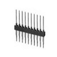
Conn Unshrouded Header HDR 40 POS 2.54mm Solder ST Thru-Hole
Manufacturer
TE Connectivity
Type
Unshrouded Headerr
Series
AMPMODU Mod IIr
Specifications of 4-103321-0
Pitch
2.54 mm
Number Of Rows
1
Number Of Contacts
40
Gender
HDR
Contact Plating
Tin-Lead Over Nickel
Termination Method
Solder
Pitch (mm)
2.54mm
Number Of Contact Rows
1
Mounting Style
Through Hole
Body Orientation
Straight
Operating Temp Range
-65C to 105C
Current Rating (max)
3/ContactA
Contact Material
Phosphor Bronze
Housing Material
Thermoplastic
Housing Color
Black
Product Height (mm)
10.37mm
Product Length (mm)
101.19mm
Product Depth (mm)
2.34mm
Pitch Spacing
2.54mm
No. Of Rows
1
No. Of Contacts
40
Contact Termination
Through Hole
Rohs Compliant
No
Product Type
Connector
Mount Angle
Vertical
Pcb Mount Retention
Without
Surface Mount Compatible
No
Board Standoff
Without
Mounting Ears
Without
Mating Connector Lock
Without
Post Size (mm [in])
0.64 [.025]
Mating Post Length (mm [in])
8.08 [0.318]
Panel Mount Retention
Without
Current Rating (a)
3
Insulation Resistance (m?)
5,000
Dielectric Withstanding Voltage (v)
750
Termination Post Length (mm [in])
3.18 [0.125]
Solder Tail Contact Plating
Tin-Lead over Nickel
Header Type
Breakaway
Number Of Positions
40
Centerline (mm [in])
2.54 [0.100]
Row-to-row Spacing (mm [in])
2.54 [0.100]
Selectively Loaded
No
Mount Type
Printed Circuit Board
Contact Plating, Mating Area, Material
Tin-Lead
Contact Shape
Square
Contact Base Material
Phosphor Bronze
Ul Flammability Rating
UL 94V-0
Rohs/elv Compliance
Not ELV/RoHS compliant
Lead Free Solder Processes
Wave solder capable to 240°C
Approved Standards
UL E28476, CSA LR7189
Operating Temperature (°c)
-65 – +105
High Temperature Housing
No
High Speed Serial Data Connector
No
Lead Free Status / RoHS Status
Not Compliant


5
198
Solder Posts and
ACTION PIN Posts
(with Pin Protection
and Guide Pins)
Material and Finish
Housing — Glass-filled thermoplastic,
black, 94V-0 rated
Posts — Phosphor bronze, plated as
follows:
Plating A — Duplex plated .000030
[0.00076] gold on contact area,
.000100-.000200 [0.00254-0.00508]
matte tin on termination end, with entire
post underplated .000050 [0.00127]
nickel
Plating B — Duplex plated .000015
[0.00038] gold on contact area,
.000100-.000200 [0.00254-0.00508]
matte tin on termination end, with entire
post underplated .000050 [0.00127]
nickel
Plating C — Selectively plated .000030
[0.00076] gold on contact area and
.000015 [0.00038] gold on termination
end, with gold flash over .000050
[0.00127] nickel on entire post
Related Product Data
Mateable Receptacles —
pages 195, 196
Performance Specifications —
page 194
ACTION PIN Posts —pages 150, 151
Application Tooling —pages 152
Technical Documents
Product Specification
108-25017
Application Specification
114-9009
Additional header sizes are
available; minimum order
quantities may apply. Consult
Tyco Electronics.
Catalog 1307819
Revised 8-08
www.tycoelectronics.com
— page 276
are metric equivalents.
Dimensions are in inches and
millimeters unless otherwise
specified. Values in brackets
AMPMODU Interconnection System
Headers, Straight Post, Double-Row, .100 x .100 [2.54 x 2.54] Centerline
Note: Headers with make first/break last posts can be made available, consult Tyco Electronics.
Note: All part numbers are RoHS compliant.
[2.79]
.110
No. of
[2.54]
Pos.
.100
100
110
120
130
200
[2.16]
[11.18]
12
14
16
20
24
30
36
40
50
60
70
72
80
86
90
96
.085
.440
[2.54±0.08]
(4 Sides)
.100±.003
[1.02]
.040
[3.30]
.130
Tolerances not to accumulate within one connector pattern.
[2.54±0.08]
.100±.003
10.380 [263.65]
1.080 [27.43]
1.180 [29.97]
1.380 [35.05]
1.580 [40.13]
1.880 [47.75]
2.180 [55.37]
2.380 [60.45]
2.880 [73.15]
3.380 [85.85]
3.880 [98.55]
3.980 [101.09]
4.380 [111.25]
4.680 [118.87]
4.880 [123.95]
5.180 [131.57]
5.380 [136.65]
5.880 [149.35]
6.380 [162.05]
6.880 [174.75]
.980 [24.89]
Recommended PC Board Hole Layout
(for .055 [1.40] min. thick PC board)
Dimensions are shown for
reference purposes only.
Specifications subject
to change.
A
1 2 3
[5.08]
Dimensions
.200
Pos.
Ref.
1.100 [27.94]
1.400 [35.56]
1.700 [43.18]
1.900 [48.26]
2.400 [60.96]
2.900 [73.66]
3.400 [86.36]
3.500 [88.90]
3.900 [99.06]
4.200 [106.68]
4.400 [111.76]
4.700 [119.38]
4.900 [124.46]
5.400 [137.16]
5.900 [149.86]
6.400 [162.56]
9.900 [251.46]
.500 [12.70]
.600 [15.24]
.700 [17.78]
.900 [22.86]
B
Board Retention Tails
B
A
(where indicated)
USA: 1-800-522-6752
Canada: 1-905-470-4425
Mexico: 01-800-733-8926
C. America: 52-55-1106-0803
6-102692-5
6-102692-6
5-102692-2
6-102692-7
5-102692-3
6-102692-3
5-102692-4
5-102692-5
6-102692-4
6-102692-8
5-102692-6
6-102692-9
6-102692-2
5-102692-7
5-102692-8
6-102692-0
5-102692-9
7-102692-0
6-102692-1
Plating A
5-102692-1
Standard Solder Tails
—
Header Part Nos. with .180 [4.57] Tail Length
(Finished Hole)
[1.02±0.08]
.040±.003
(Drilled Hole)
.0453±.001
[1.02±0.03]
5-102567-1
7-102567-3
6-102567-1
5-102567-2
6-102567-3
5-102567-3
6-102567-2
5-102567-6
5-102567-4
6-102567-0
6-102567-6
5-102567-8
6-102567-7
6-102567-4
5-102567-5
5-102567-9
6-102567-5
5-102567-7
6-102567-9
7-102567-1
Plating B
—
[8.13]
.320
[1.66]
.065
(2 Plc.)
(2 Plc.)
Gold Plate
[4.57]
(Localized
[3.30]
.180
.130
South America: 55-11-2103-6000
Hong Kong: 852-2735-1628
Japan: 81-44-844-8013
UK: 44-8706-080-208
[5.08]
Area)
.200
R
6-534978-6
5-534978-2
5-534978-3
5-534978-4
5-534978-5
5-534978-6
5-534978-7
5-534978-8
5-534978-9
6-534978-5
6-534978-0
6-534978-1
6-534978-7
6-534978-8
6-534978-2
6-534978-3
6-534978-9
5-534978-1
Plating A
[4.57]
[13.08]
.180
Board Retention Tails
Board Retention Tails
.515
.025 [0.64] Square
—
—
—
5-534257-5
6-534257-4
5-534257-6
5-534257-7
5-534257-8
5-534257-9
6-534257-0
6-534257-5
6-534257-1
6-534257-2
5-534257-1
5-534257-2
5-534257-3
6-534257-9
Plating B
—
—
—
—
—
—
—
[2.29]
.090
Related parts for 4-103321-0
Image
Part Number
Description
Manufacturer
Datasheet
Request
R

Part Number:
Description:
Conn IDC Connector F 10 POS 2.54mm IDT RA Cable Mount Loose Piece
Manufacturer:
TE Connectivity
Datasheet:

Part Number:
Description:
Conn IDC Connector F 10 POS 2.54mm IDT RA Cable Mount Loose Piece
Manufacturer:
TE Connectivity
Datasheet:

Part Number:
Description:
TERMINAL FEMALE DISCONNECT 6.35MM YELLOW
Manufacturer:
TE Connectivity
Datasheet:

Part Number:
Description:
TERMINAL FEMALE DISCONNECT 6.35MM YELLOW
Manufacturer:
TE Connectivity
Datasheet:

Part Number:
Description:
BOX HEADER STRAIGHT 40 WAY
Manufacturer:
TE Connectivity
Datasheet:

Part Number:
Description:
Manufacturer:
TE Connectivity
Datasheet:

Part Number:
Description:
Manufacturer:
TE Connectivity
Datasheet:

Part Number:
Description:
RES 390 OHM 1W 5% 2512
Manufacturer:
TE Connectivity
Datasheet:
Part Number:
Description:
Electromechanical Relay 3PST-NO/SPST-NC 8A 24VDC 720Ohm Through Hole
Manufacturer:
TE Connectivity
Datasheet:
Part Number:
Description:
ADF08ST04=DIP SWT,FLUSH,SMT-GW
Manufacturer:
TE Connectivity
Datasheet:

Part Number:
Description:
CRIMP PIN, SILVER, 1.5MM
Manufacturer:
TE Connectivity
Datasheet:

Part Number:
Description:
CRIMP SOCKET, 1.5MM
Manufacturer:
TE Connectivity
Datasheet:
Part Number:
Description:
Manufacturer:
TE Connectivity
Datasheet:
Part Number:
Description:
Res Thick Film 2512 3.3K Ohm 5% 1W ±200ppm/°C Molded SMD T/R
Manufacturer:
TE Connectivity
Datasheet:
Part Number:
Description:
Conn IDC Connector F 14 POS 2.54mm IDT RA Cable Mount Loose Piece
Manufacturer:
TE Connectivity
Datasheet: