1-794066-0 TE Connectivity, 1-794066-0 Datasheet - Page 5
1-794066-0
Manufacturer Part Number
1-794066-0
Description
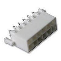
Conn Wire to Board PIN 12 POS 4.14mm Solder ST Thru-Hole
Manufacturer
TE Connectivity
Type
Wire to Boardr
Series
Mini-Universal MATE-N-LOK 2r
Specifications of 1-794066-0
Pitch
4.14 mm
Number Of Rows
2
Number Of Contacts
12
Gender
PIN
Contact Plating
Tin Over Nickel
Termination Method
Solder
Connector Type
Plug & Socket
Pitch Spacing
4.14mm
No. Of Contacts
12
No. Of Rows
2
Connector Mounting
PCB
Contact Material
Brass
Rohs Compliant
Yes
Product Type
Headers - Shrouded
Contact Gender
Pin (Male)
Number Of Positions / Contacts
12
Row Spacing
4.14 mm
Mounting Style
Through Hole
Mounting Angle
Vertical
Latching Type
Latched
Termination Style
Solder Pin
Housing Material
Nylon
Voltage Rating
600 V
Current Rating
9.5 A
Connector Line
Mini-Universal MATE-N-LOK, Mini-Universal MATE-N-LOK 2
Mount
Printed Circuit Board
Color
White
Pcb Mount Retention
With
Mount Angle
Vertical
Mating Retention Type
Detent Lock
Voltage (vac)
600
Current Rating (a)
9.5
Termination Post Length (mm [in])
3.68 [0.145]
Solder Tail Contact Plating
Matte Tin over Nickel
Centerline (mm [in])
4.14 [0.163]
Number Of Positions
12
Mating Retention
With
Contact Diameter (mm [in])
0.99 [0.039]
Pcb Mount Retention Type
Boardlock(s)
Contact Type
Pin
Contact Termination Type
Through Hole
Contact Layout
Double-Row
Contact Base Material
Brass
Contact Plating, Mating Area, Material
Matte Tin
Solder Process Drain Hole
With
Connector Style
Plug
Ul Flammability Rating
UL 94V-0
Rohs/elv Compliance
RoHS compliant, ELV compliant
Lead Free Solder Processes
Wave solder capable to 240°C, Wave solder capable to 260°C, Wave solder capable to 265°C
Rohs/elv Compliance History
Always was RoHS compliant
Applies To
Printed Circuit Board
Pcb Thickness, Recommended (mm [in])
1.57 [0.062]
Lead Free Status / Rohs Status
Details
Available stocks
Company
Part Number
Manufacturer
Quantity
Price
Company:

Part Number:
1-794066-0
Manufacturer:
TE
Quantity:
20 000


3.3. Assembly
A crimped contact (pin or socket) must be inserted into the housing by aligning it with the desired contact cavity
in the BACK (wire side) of the housing. The wire must be grasped directly behind the insulation barrel and the
contact pushed straight into the contact cavity until the contact bottoms (there will be an audible click).
The wire must be pulled back lightly to ensure that the contact is locked in place.
3.4. Panel Mounting (Cap Housing)
Up--and--Down
Side--to--Side
Rev L
CAUTION
G. Wire Barrel Seam
The wire barrel seam shall be closed adequately to confine all strands of the wire. There shall be no loose
strands. Wire strands should not be embedded in the outside of the wire barrel.
H. Straightness
The contact, including the cutoff tab, shall not be bent above or below the datum line more than the
amount shown in Figure 3.
I. Twist and Roll
There shall be no twist or roll in crimped portion that will impair usage of the contact. See Figure 3.
A. Thickness
The panel thickness range shall be 0.79 through 2.01 [.031 through .079].
B. Cutout
The dimensions of the panel cutout for panel mounting is provided in Figure 4.
!
Note: Not to Scale
Excessive force must NOT be used when inserting the contact into the contact cavity. The contact stop of the contact
is designed to ensure proper insertion depth of the contact. Over--insertion will cause damage to the contact or contact
cavity of the housing and prevent the contact from floating in the contact cavity, which is necessary for optimum
performance of the connector.
10_ Max
Twist and Roll
Straightness
Figure 3
10_ Max
Datum Line
4_ Max
4_ Max
4_ Max
Datum Line
Datum Line
114- - 16017
5 of 12
Related parts for 1-794066-0
Image
Part Number
Description
Manufacturer
Datasheet
Request
R

Part Number:
Description:
CB-1014B-79=TIME DELAY REL
Manufacturer:
Tyco Electronics
Datasheet:

Part Number:
Description:
CONN FPC 13POS 1MM RT ANG SMD
Manufacturer:
TE Connectivity
Datasheet:
Part Number:
Description:
CONN FPC 15POS 1MM RT ANG SMD
Manufacturer:
TE Connectivity
Datasheet:

Part Number:
Description:
CONN FPC 14POS 1.00MM R/A SMD
Manufacturer:
Tyco Electronics
Datasheet:

Part Number:
Description:
CONN FPC 12POS 1.00MM R/A SMD
Manufacturer:
Tyco Electronics
Datasheet:

Part Number:
Description:
Manufacturer:
TE Connectivity
Datasheet:

Part Number:
Description:
INSERT, MALE, SCREW, 16-32
Manufacturer:
TE Connectivity
Datasheet:

Part Number:
Description:
INSERT, FEMALE, SCREW TERM, 16-32WAY
Manufacturer:
TE Connectivity
Datasheet:

Part Number:
Description:
FFC/FPC CONNECTOR, RECEPTACLE 20POS 1ROW
Manufacturer:
TE Connectivity
Datasheet:

Part Number:
Description:
Conn D-Subminiature SKT 9 POS 2.74mm IDT ST Cable Mount 9 Terminal 1 Port
Manufacturer:
TE Connectivity
Datasheet:

Part Number:
Description:
HOUSING, SURFACE MOUNT, SIZE 1
Manufacturer:
TE Connectivity
Datasheet:

Part Number:
Description:
Conn D-Subminiature RCP 9 POS 2.74mm Solder ST Thru-Hole 9 Terminal 1 Port
Manufacturer:
TE Connectivity

Part Number:
Description:
FAST ISO-HUELSE6,3
Manufacturer:
TE Connectivity
Datasheet:
Part Number:
Description:
Manufacturer:
TE Connectivity
Datasheet:
Part Number:
Description:
Manufacturer:
TE Connectivity
Datasheet: