5-103904-3 TE Connectivity, 5-103904-3 Datasheet - Page 2
5-103904-3
Manufacturer Part Number
5-103904-3
Description
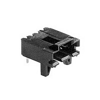
Conn Shrouded Header HDR 4 POS 2.54mm Solder RA Thru-Hole Tube
Manufacturer
TE Connectivity
Type
Shrouded Headerr
Series
AMPMODU MTEr
Specifications of 5-103904-3
Pitch
2.54 mm
Number Of Rows
1
Number Of Contacts
4
Gender
HDR
Contact Plating
Gold Over Nickel
Termination Method
Solder
Connector Type
Wire To Board
Contact Termination
Right Angle Through Hole
No. Of Contacts
4
No. Of Rows
1
Pitch Spacing
2.54mm
Rohs Compliant
Yes
Agency Approvals
CSA, UL
Angle
Right
Brand/series
AMPMODU/MTE Series
Color
Black
Current, Rating
3 A
Flammability Rating
UL94V-0
Length, Overall
0.5 "
Material, Contact
Brass
Material, Housing
Thermoplastic
Pin Spacing
0.1 "
Primary Type
Interconnect System
Special Features
Breakaway
Temperature, Operating
-65 to +105 °C
Termination
Thru-Hole
Product Type
Plugs - PCB
Contact Gender
Pin (Male)
Number Of Positions / Contacts
4
Row Spacing
2.54 mm
Mounting Style
Through Hole
Mounting Angle
Right
Termination Style
Crimp
Housing Material
Thermoplastic, Glass Filled
Contact Material
Brass
Current Rating
3 A
Operating Temperature Range
- 65 C to + 105 C
Post Size (mm [in])
0.64 [.025]
Pcb Mounting Orientation
Right Angle
Termination Method To Wire/cable
Crimp, Insulation Displacement Crimp (IDC)
Pcb Mount Style
Through Hole
Pcb Mount Retention
With
Connector Series
MTE
Contact - Rated Current (a)
3
Termination Resistance (m?)
15
Insulation Resistance (m?)
5,000
Dielectric Withstanding Voltage (v)
600
Solder Tail Contact Plating
Tin
Centerline (mm [in])
2.54 [0.100]
Row-to-row Spacing (mm [in])
2.54 [0.100]
Number Of Positions
4
Contact Type
Pin
Pcb Orientation Feature
No
Contact Plating, Mating Area, Material
Gold (30)
Contact Base Material
Brass
Contact Shape
Square
Connector Style
Plug
Mating Alignment
With
Mating Alignment Type
Latched
Housing Color
Black
Ul Flammability Rating
UL 94V-0
Rohs/elv Compliance
RoHS compliant, ELV compliant
Lead Free Solder Processes
Wave solder capable to 240°C, Wave solder capable to 260°C, Wave solder capable to 265°C
Rohs/elv Compliance History
Always was RoHS compliant
Approved Standards
UL E28476, CSA LR7189
Operating Temperature (°c)
-65 – +105
Applies To
Printed Circuit Board
Temperature Rating
High
Packaging Method
Tube
Lead Free Status / Rohs Status
RoHS Compliant part


5
182
Dual Entry, End Stackable,
Low Profile, .100 x .100
[2.54 x 2.54] Centerline,
.300 [7.62] Tine Spacing
Material and Finish
Housing — Glass-filled thermoplastic,
black, 94V-0 rated
Contacts — Phosphor bronze,
plated as follows:
Plating A — Duplex .000030 [0.00076]
gold on contact area, .000150-.000300
[0.00381-0.00762] matte tin on solder
area all over .000050 [0.00127] nickel
Plating B — Duplex .000010
[0.000254] gold on contact area,
.000150-.000300 [0.00381-0.00762]
matte tin on solder area all over .000050
[0.00127] nickel
Plating C — .000150-.000300
[0.00381-0.00762] matte tin on solder
leads, all over .000050 [0.00127] nickel
Related Product Data
Mateable Headers —
Refer to the Mating Post Selection
Guide — page 90
Performance Characteristics —
page 174
Technical Documents
Product Specification
108-25022
Application Specification
114-25018
Additional receptacle assembly
sizes are available; minimum
order quantities may apply.
Consult Tyco Electronics.
Material — Natural color nylon
Catalog 1307819
Revised 8-08
www.tycoelectronics.com
Keying Plug
(Plugs into receptacle contact)
Part No. 86286-1
— page 276
are metric equivalents.
Dimensions are in inches and
millimeters unless otherwise
specified. Values in brackets
AMPMODU Interconnection System
Mod IV Receptacle Assemblies, Double-Row, Outrigger Design,
.100 x .100 [2.54 x 2.54] Centerline, End to End Stackable
[5.03]
Notes: 1. Tyco Electronics recommends mating gold or duplex plated headers with duplex plated receptacle assemblies.
Note: All part numbers are RoHS compliant.
.198
[1.27]
Max.
.050
Typ.
No. of
Pos.
14
18
20
24
30
36
40
48
50
60
76
80
2
4
6
8
2. To obtain the minimum mating post length, add .020 [0.51] (not including the post lead in chamfer) to the
maximum point-of-contact dimension and .062 for recommended board thickness if used in bottom entry
application.
1.000 [25.40]
1.200 [30.48]
1.500 [38.10]
1.800 [45.72]
2.000 [50.80]
2.400 [60.96]
2.500 [63.50]
3.000 [76.20]
3.800 [96.52]
4.000 [101.60]
.100 [2.54]
.200 [5.08]
.300 [7.62]
.400 [10.16]
.700 [17.78]
.900 [22.86]
[2.54]
Dimensions are shown for
reference purposes only.
Specifications subject
to change.
.100
Typ.
A
[0.89
.035
±.003
±0.08
Dimensions
A
[2.54]
.100
Typ.
]
Dia.
Typ.
Recommended PC Board Hole Layout
1.100 [27.94]
1.400 [35.56]
1.700 [43.18]
1.900 [48.26]
2.300 [58.42]
2.400 [60.96]
2.900 [73.66]
3.700 [93.98]
3.900 [99.06]
.100 [2.54]
.200 [5.08]
.300 [7.62]
.600 [15.24]
.800 [20.32]
.900 [22.86]
—
B
[6.22]
USA: 1-800-522-6752
Canada: 1-905-470-4425
Mexico: 01-800-733-8926
C. America: 52-55-1106-0803
.245
Typ.
[2.54±0.08]
(Standoffs)
.100±.003
B
[0.51]
.020
6-534267-3
6-534267-7
6-534267-4
5-534267-5
5-534267-1
6-534267-0
5-534267-2
5-534267-9
6-534267-2
6-534267-5
5-534267-7
6-534267-1
6-534267-8
5-534267-8
6-534267-6
5-534267-4
Plating A
[
.075
1.90
.060
+.005
+0.13
-0.00
-0.00
(Localized Gold
Contact Plating/Part Nos.
]
Plate Area)
Dia.
Typ.
[2.72]
.107
Typ.
[3.77]
.148
Typ.
[2.54]
.100
Typ.
5-147099-1
5-147099-2
5-147099-3
5-147099-4
5-147099-7
5-147099-9
6-147099-0
6-147099-2
6-147099-5
6-147099-8
7-147099-0
7-147099-4
7-147099-5
8-147099-0
8-147099-8
9-147099-0
Plating B
South America: 55-11-2103-6000
Hong Kong: 852-2735-1628
Japan: 81-44-844-8013
UK: 44-8706-080-208
[2.54]
.100
Typ.
[2.54]
.100
Typ.
Contact
Point of
8-147100-9
9-147100-0
5-147100-1
5-147100-2
5-147100-5
5-147100-7
5-147100-8
6-147100-0
6-147100-3
6-147100-6
6-147100-8
7-147100-2
7-147100-3
7-147100-8
8-147100-6
8-147100-8
Plating C
[3.17±0.25]
.125±.010
[7.62]
.300
Typ.
Related parts for 5-103904-3
Image
Part Number
Description
Manufacturer
Datasheet
Request
R

Part Number:
Description:
Conn Unshrouded Header HDR 10 POS 2.54mm Solder ST SMD
Manufacturer:
TE Connectivity
Datasheet:

Part Number:
Description:
Conn Shrouded Header HDR 10 POS 2.54mm Solder ST Thru-Hole
Manufacturer:
TE Connectivity
Datasheet:

Part Number:
Description:
Conn Shrouded Header HDR 10 POS 2.54mm Solder ST Thru-Hole
Manufacturer:
TE Connectivity
Datasheet:

Part Number:
Description:
Conn Unshrouded Header HDR 10 POS 2.54mm Solder ST SMD
Manufacturer:
TE Connectivity
Datasheet:

Part Number:
Description:
STACKING CONN, HEADER, 10POS, 1.27MM
Manufacturer:
TE Connectivity
Datasheet:

Part Number:
Description:
Manufacturer:
TE Connectivity
Datasheet:

Part Number:
Description:
Manufacturer:
TE Connectivity
Datasheet:

Part Number:
Description:
Conn Shrouded Header HDR 4 POS 2.54mm Solder ST Thru-Hole
Manufacturer:
TE Connectivity
Datasheet:

Part Number:
Description:
Conn Shrouded Header HDR 3 POS 2.54mm Solder RA Thru-Hole
Manufacturer:
TE Connectivity
Datasheet:

Part Number:
Description:
Conn Shrouded Header HDR 3 POS 2.54mm Solder ST Thru-Hole
Manufacturer:
TE Connectivity
Datasheet:

Part Number:
Description:
Conn Shrouded Header HDR 2 POS 2.54mm Solder ST Thru-Hole Tube
Manufacturer:
TE Connectivity
Datasheet:

Part Number:
Description:
Conn IDC Connector PIN 2 POS 2.54mm IDT ST Cable Mount Strip
Manufacturer:
TE Connectivity
Datasheet:

Part Number:
Description:
Conn IDC Connector RCP 2 POS 2.54mm IDT ST Cable Mount Strip
Manufacturer:
TE Connectivity
Datasheet:

Part Number:
Description:
Conn Shrouded Header HDR 2 POS 2.54mm Solder ST Thru-Hole Tube
Manufacturer:
TE Connectivity
Datasheet:

Part Number:
Description:
Conn Shrouded Header HDR 2 POS 2.54mm Solder ST Thru-Hole Tube
Manufacturer:
TE Connectivity
Datasheet: