103308-2 TE Connectivity, 103308-2 Datasheet - Page 117
103308-2
Manufacturer Part Number
103308-2
Description
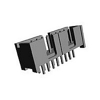
Conn Shrouded Header HDR 14 POS 2.54mm Solder ST Thru-Hole
Manufacturer
TE Connectivity
Type
Shrouded Headerr
Specifications of 103308-2
Pitch
2.54 mm
Number Of Rows
2
Number Of Contacts
14
Gender
HDR
Contact Plating
Gold Over Nickel/Gold Over Palladium Nickel
Termination Method
Solder
Pitch (mm)
2.54mm
Number Of Contact Rows
2
Mounting Style
Through Hole
Body Orientation
Straight
Operating Temp Range
-65C to 105C
Current Rating (max)
1/ContactA
Contact Material
Copper Alloy
Housing Material
Thermoplastic
Housing Color
Black
Product Height (mm)
9.77mm
Product Length (mm)
25.4mm
Product Depth (mm)
9.14mm
Rohs Compliant
NO
Product Line
AMP-LATCH
Profile
Low
Pcb Mounting Orientation
Vertical
Pcb Mount Retention
Without
Mating Connector Lock
Without
Housing Style
4-Sided
Ejection Latches
Without
Post Size (mm [in])
0.64 [.025]
Shrouded
Yes
[shrouded] End Dimension (mm [in])
3.81 [0.150]
Current Rating (a)
1
Insulation Resistance (m?)
5,000
Termination Post Length (mm [in])
3.05 [0.120]
Solder Tail Contact Plating
Tin-Lead over Nickel
Header Type
Pin Header
Number Of Positions
14
Centerline, Matrix (mm [in])
2.54 x 2.54 [.100 x .100]
Daisy Chain
With
Preloaded
Yes
Contact Plating, Mating Area, Material
Gold (15), Gold Flash over Palladium Nickel
Contact Shape
Square
Contact Base Material
Copper Alloy
Connector Style
Header - Pin
Mating Alignment Type
Center, Dual Polarizing Bar
Mating Alignment
With
Ul Flammability Rating
UL 94V-0
Rohs/elv Compliance
ELV compliant, 5 of 6 Compliant
Lead Free Solder Processes
Not suitable for lead free processing
Approved Standards
UL E28476, CSA LR7189
Operating Temperature (°c)
-65 – +105
Temperature Rating
Standard
Lead Free Status / RoHS Status
Not Compliant


5
200
Catalog 1307819
Revised 6-04
www.tycoelectronics.com
Closed Dual Entry, Side and
End Stackable Low Profile,
.100 x .100 [2.54 x 2.54]
Centerline, .150 [3.81] Tine
S p a c i n g
Photo 110925
Material and Finish:
Housing—Black thermoplastic,
94V-0 rated
Contacts—Phosphor bronze,
plated as follows:
Plating A—Duplex .000030 [0.00076]
gold on contact area, .000150-.000300
[0.00381-0.00762] tin-lead on solder
area all over .000050 [0.00127] nickel
Plating B—Duplex .000010
[0.000254] gold on contact area,
.000150-.000300 [0.00381-0.00762]
tin-lead on solder area all over .000050
[0.00127] nickel
Plating C—.000100-.000200
[0.00254-0.00508] tin-lead over
.000050 [0.00127] nickel
Related Product Data:
Mateable Headers—Refer
to the Mating Post Selection Guide
(page 89)
Performance Characteristics—page
191
Technical Documents
Product Specification 108-25022
Application Specification
114-25018
(page 294):
Dimensions are in inches and
millimeters unless otherwise
specified. Values in brackets
are metric equivalents.
[
.075
.060
1.90
AMPMODU Interconnection System
[5.03]
Notes: 1. Tyco Electronics recommends mating gold or duplex plated headers with duplex plated receptacle
Mod. IV Receptacle Assemblies, Double-Row,
.100 x .100 [2.54 x 2.54] Centerline
.198
No. of
P o s .
+.005
+0.13
-.000
- 0.00
[2.54]
1 0
1 2
1 4
1 6
1 8
2 0
2 2
2 4
2 6
2 8
3 0
3 2
3 4
3 6
3 8
4 0
.100
2
4
6
8
]
2. To obtain the minimum mating post length, add .020 [0.51] (not including the post lead in chamfer) to
for Bottom Entry or Pass Through Applications
Typ.
Dia.
assemblies.
the maximum point-of-contact dimension, and .062 [1.57] for recommended board thickness if used in
bottom entry application.
*±.003 [±0.08] tolerances not to accumulate
Recommended PC Board Hole Layout
1 . 0 0 0 [ 2 5 . 4 0 ]
1 . 1 0 0 [ 2 7 . 9 4 ]
1 . 2 0 0 [ 3 0 . 4 8 ]
1 . 3 0 0 [ 3 3 . 0 2 ]
1 . 4 0 0 [ 3 5 . 5 6 ]
1 . 5 0 0 [ 3 8 . 1 0 ]
1 . 6 0 0 [ 4 0 . 6 4 ]
1 . 7 0 0 [ 4 3 . 1 8 ]
1 . 8 0 0 [ 4 5 . 7 2 ]
1 . 9 0 0 [ 4 8 . 2 6 ]
2 . 0 0 0 [ 5 0 . 8 0 ]
.100 [ 2 . 5 4 ]
. 2 0 0 [ 5 . 0 8 ]
. 3 0 0 [ 7 . 6 2 ]
. 4 0 0 [ 1 0 . 1 6 ]
. 5 0 0 [ 1 2 . 7 0 ]
. 6 0 0 [ 1 5 . 2 4 ]
. 7 0 0 [ 1 7 . 7 8 ]
. 8 0 0 [ 2 0 . 3 2 ]
. 9 0 0 [ 2 2 . 8 6 ]
[1.27]
Max.
.050
Typ.
within one connector pattern.
A
Dimensions are shown for
reference purposes only.
Specifications subject
to change.
D i m e n s i o n s
[2.54]
B
A
.100
Typ.
1 . 0 0 0 [ 2 5 . 4 0 ]
1 . 1 0 0 [ 2 7 . 9 4 ]
1 . 2 0 0 [ 3 0 . 4 8 ]
1 . 3 0 0 [ 3 3 . 0 2 ]
1 . 4 0 0 [ 3 5 . 5 6 ]
1 . 5 0 0 [ 3 8 . 1 0 ]
1 . 6 0 0 [ 4 0 . 6 4 ]
1 . 7 0 0 [ 4 3 . 1 8 ]
1 . 8 0 0 [ 4 5 . 7 2 ]
1 . 9 0 0 [ 4 8 . 2 6 ]
. 1 0 0 [ 2 . 5 4 ]
.200 [ 5 . 0 8 ]
. 3 0 0 [ 7 . 6 2 ]
. 4 0 0 [ 1 0 . 1 6 ]
. 5 0 0 [ 1 2 . 7 0 ]
. 6 0 0 [ 1 5 . 2 4 ]
. 7 0 0 [ 1 7 . 7 8 ]
. 8 0 0 [ 2 0 . 3 2 ]
. 9 0 0 [ 2 2 . 8 6 ]
B
—
USA: 1-800-522-6752
Canada: 1-905-470-4425
Mexico: 01-800-733-8926
C. America: 52-55-5-729-0425
[6.22]
.245
Typ.
(Standoffs)
[2.54±0.08]
.100±.003
[0.51]
.020
Typ.
[2.54]
.100
Typ.
1 - 5 3 5 5 4 2 - 0
1 - 5 3 5 5 4 2 - 1
1 - 5 3 5 5 4 2 - 2
1 - 5 3 5 5 4 2 - 3
1 - 5 3 5 5 4 2 - 4
1 - 5 3 5 5 4 2 - 5
1 - 5 3 5 5 4 2 - 6
1 - 5 3 5 5 4 2 - 7
1 - 5 3 5 5 4 2 - 8
1 - 5 3 5 5 4 2 - 9
2 - 5 3 5 5 4 2 - 0
[0.89±0.08]
Plating A
.035±.003
5 3 5 5 4 2 - 1
5 3 5 5 4 2 - 2
5 3 5 5 4 2 - 3
5 3 5 5 4 2 - 4
5 3 5 5 4 2 - 5
5 3 5 5 4 2 - 6
5 3 5 5 4 2 - 7
5 3 5 5 4 2 - 8
5 3 5 5 4 2 - 9
(Localized Gold
Plate Area)
Recommended PC Board Hole Layout
[3.77]
[2.72]
.107
Typ.
.148
Typ.
Dia. Typ.
Contact Plating/Part Nos.
[2.54]
.100
Typ.
South America: 55-11-3611-1514
Hong Kong: 852-2735-1628
Japan: 81-44-844-8013
UK: 44-141-810-8967
1 - 1 4 7 0 9 5 - 0
1 - 1 4 7 0 9 5 - 1
1 - 1 4 7 0 9 5 - 2
1 - 1 4 7 0 9 5 - 3
1 - 1 4 7 0 9 5 - 4
1 - 1 4 7 0 9 5 - 5
1 - 1 4 7 0 9 5 - 6
1 - 1 4 7 0 9 5 - 7
1 - 1 4 7 0 9 5 - 8
1 - 1 4 7 0 9 5 - 9
2 - 1 4 7 0 9 5 - 0
for Top Entry
Plating B
1 4 7 0 9 5 - 1
1 4 7 0 9 5 - 2
1 4 7 0 9 5 - 3
1 4 7 0 9 5 - 4
1 4 7 0 9 5 - 5
1 4 7 0 9 5 - 6
1 4 7 0 9 5 - 7
1 4 7 0 9 5 - 8
1 4 7 0 9 5 - 9
Point of
Contact
B
[3.30±0.25]
1 - 1 4 7 0 9 6 - 0
1 - 1 4 7 0 9 6 - 1
1 - 1 4 7 0 9 6 - 2
1 - 1 4 7 0 9 6 - 3
1 - 1 4 7 0 9 6 - 4
1 - 1 4 7 0 9 6 - 5
1 - 1 4 7 0 9 6 - 6
1 - 1 4 7 0 9 6 - 7
1 - 1 4 7 0 9 6 - 8
1 - 1 4 7 0 9 6 - 9
2 - 1 4 7 0 9 6 - 0
.130±.010
Plating C
1 4 7 0 9 6 - 1
1 4 7 0 9 6 - 2
1 4 7 0 9 6 - 3
1 4 7 0 9 6 - 4
1 4 7 0 9 6 - 5
1 4 7 0 9 6 - 6
1 4 7 0 9 6 - 7
1 4 7 0 9 6 - 8
1 4 7 0 9 6 - 9
[3.81]
.150
Typ.
Typ.
[3.81]
.150
Typ.
Related parts for 103308-2
Image
Part Number
Description
Manufacturer
Datasheet
Request
R

Part Number:
Description:
Conn Shrouded Header HDR 10 POS 2.54mm Solder ST Thru-Hole
Manufacturer:
TE Connectivity
Datasheet:

Part Number:
Description:
Conn Shrouded Header HDR 16 POS 2.54mm Solder ST Thru-Hole
Manufacturer:
TE Connectivity
Datasheet:

Part Number:
Description:
Conn Shrouded Header HDR 26 POS 2.54mm Solder ST Thru-Hole
Manufacturer:
TE Connectivity
Datasheet:
Part Number:
Description:
Conn Shrouded Header HDR 40 POS 2.54mm Solder ST Thru-Hole
Manufacturer:
TE Connectivity
Datasheet:
Part Number:
Description:
Conn Shrouded Header HDR 20 POS 2.54mm Solder ST Thru-Hole
Manufacturer:
TE Connectivity
Datasheet:

Part Number:
Description:
High Speed / Modular Connectors 30P HEADER ASSY
Manufacturer:
TE Connectivity
Datasheet:

Part Number:
Description:
High Speed / Modular Connectors REC 6X005P R/A LT B-PLANE HS3
Manufacturer:
TE Connectivity
Datasheet:

Part Number:
Description:
High Speed / Modular Connectors 2MM HM RCPT 50P R/A AU
Manufacturer:
TE Connectivity
Datasheet:

Part Number:
Description:
High Speed / Modular Connectors 2MM HM RCPT 50P R/A AU
Manufacturer:
TE Connectivity
Datasheet:


Part Number:
Description:
Manufacturer:
TE Connectivity
Datasheet:


Part Number:
Description:
Manufacturer:
TE Connectivity
Datasheet:

Part Number:
Description:
Manufacturer:
TE Connectivity
Datasheet:

Part Number:
Description:
Manufacturer:
TE Connectivity
Datasheet: