1-1761606-3 TE Connectivity, 1-1761606-3 Datasheet - Page 82
1-1761606-3
Manufacturer Part Number
1-1761606-3
Description
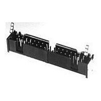
Conn Shrouded Header HDR 40 POS 2.54mm Solder ST Thru-Hole
Manufacturer
TE Connectivity
Type
Shrouded Headerr
Series
AMP-LATCHr
Specifications of 1-1761606-3
Pitch
2.54 mm
Number Of Rows
2
Number Of Contacts
40
Gender
HDR
Contact Plating
Gold Over Nickel
Termination Method
Solder
Connector Type
Wire To Board
Contact Termination
Right Angle Through Hole
No. Of Contacts
40
No. Of Rows
2
Pitch Spacing
2.54mm
Rohs Compliant
Yes
Product Line
AMP-LATCH
Profile
Low
Pcb Mounting Orientation
Vertical
Pcb Mount Retention
Without
Mating Connector Lock
Without
Housing Style
4-Sided
Ejection Latches
With
Post Size (mm [in])
0.64 [.025]
Shrouded
Yes
[shrouded] End Dimension (mm [in])
3.81 [0.150]
Termination Post Length (mm [in])
2.60 [0.102]
Solder Tail Contact Plating
Tin over Nickel
Header Type
Pin Header
Number Of Positions
40
Centerline, Matrix (mm [in])
2.54 x 2.54 [.100 x .100]
Daisy Chain
With
Preloaded
Yes
Contact Plating, Mating Area, Material
Gold Flash over Palladium Nickel
Contact Shape
Square
Contact Base Material
Phosphor Bronze
Connector Style
Header - Pin
Mating Alignment Type
Center, Military
Mating Alignment
With
Housing Material
Nylon
Ul Flammability Rating
UL 94V-0
Housing Color
Black
Rohs/elv Compliance
RoHS compliant, ELV compliant
Lead Free Solder Processes
Wave solder capable to 240°C, Wave solder capable to 260°C, Wave solder capable to 265°C
Rohs/elv Compliance History
Always was RoHS compliant
Temperature Rating
Standard
Lead Free Status / Rohs Status
RoHS Compliant part


2
Note: All part numbers are RoHS compliant.
(Soldertail
Length)
Dim. C
.102
2.59
.165
4.19
No. of
Pos.
10
14
16
20
24
26
30
34
40
50
60
10
14
16
20
24
26
34
40
50
1.250 [31.75]
1.450 [36.83]
1.550 [39.37]
1.750 [44.45]
2.050 [52.07]
2.250 [57.15]
2.450 [62.23]
2.750 [69.85]
3.250 [82.55]
3.750 [95.25]
1.250 [31.75]
1.450 [36.83]
1.550 [39.37]
1.750 [44.45]
2.050 [52.07]
2.450 [62.23]
2.750 [69.85]
3.250 [82.55]
1.950[49.53]
1.950[49.53]
A
Dimensions
View for Clarity
[8.89]
[8.89]
Eject Latches
Not Shown in
Top and Side
.350
.350
[0.33]
[8.89
.013
.350
Position #1 Indicator
Position #1 Indicator
1.100 [27.94]
1.200 [30.48]
1.400 [35.56]
1.600 [40.64]
1.900 [48.26]
2.400 [60.96]
2.900 [73.66]
1.100 [27.94]
1.200 [30.48]
1.600 [40.64]
1.900 [48.26]
2.400 [60.96]
[0.33]
[0.33]
+ .005
– .010
+ 0.13
– 0.25
.400 [10.16]
.600 [15.24]
.700 [17.78]
.900 [22.86]
.400 [10.16]
.600 [15.24]
.700 [17.78]
.900 [22.86]
.013
.013
]
B
Pin 2
1-1761693-1
1-1761693-6
Pin Header
[0.63
.025
1761693-3
1761693-8
1761694-3
1761694-9
Latches
without
—
—
—
—
—
—
—
—
—
—
—
—
—
—
± .001
± 0.03
[2.54]
Without Latches
.100
With Latches
]
Pin 1
Recommended PC Board Layout
A
A
B
U
U
U
U
Pin Header with Short Latches
[0.63
.025
(Mates with Receptacles
without Strain Relief)
± .001
± 0.03
Ø .035
[0.89
1-1761685-0
1-1761685-1
1-1761685-3
1-1761685-5
1-1761685-6
1-1761687-1
1-1761687-3
]
1761685-3
1761685-6
1761685-7
1761685-8
1761685-9
1761687-3
1761687-7
1761687-9
± .003
± 0.08
—
—
—
—
—
]
[14.62
[10.64
.576
.419
Part Numbers
[2.54]
± .006
± .006
.100
± 0.15
± 0.15
[20.98
[16.89
.826
.665
[6.40
[2.54]
]
]
.100
.252
Long
Short
± .020
± .020
± 0.51
± 0.51
+ .010
– .004
+ 0.25
– 0.10
Pin Header with Long Latches
]
]
[0.63
.025
Long
Short
(Mates with Receptacles
]
Ø .031
with Strain Relief)
[0.79]
± .001
± 0.03
Max.
1-1761686-1
1-1761686-3
1-1761686-5
1-1761688-1
1-1761688-5
Section U-U
]
1761686-3
1761686-5
1761686-6
1761686-7
1761686-8
1761686-9
1761688-7
1761688-8
1761688-9
—
—
—
—
—
—
C
[
[6.10
± .015
± 0.38
.240
± .010
± 0.25
]
]
Related parts for 1-1761606-3
Image
Part Number
Description
Manufacturer
Datasheet
Request
R

Part Number:
Description:
CONTACT, MCP 2.8, 17-13AWG
Manufacturer:
TE Connectivity
Datasheet:

Part Number:
Description:
250 FASTON IS
Manufacturer:
TE Connectivity
Datasheet:

Part Number:
Description:
MCP2,8 RECEPTACLE CONTACT
Manufacturer:
TE Connectivity
Datasheet:
Part Number:
Description:
CRIMP, RECEPTACLE
Manufacturer:
TE Connectivity
Datasheet:

Part Number:
Description:
Manufacturer:
TE Connectivity
Datasheet:

Part Number:
Description:
Manufacturer:
TE Connectivity
Datasheet:

Part Number:
Description:
Manufacturer:
TE Connectivity
Datasheet:

Part Number:
Description:
Manufacturer:
TE Connectivity
Datasheet:

Part Number:
Description:
Manufacturer:
TE Connectivity
Datasheet:

Part Number:
Description:
Manufacturer:
TE Connectivity
Datasheet:

Part Number:
Description:
Manufacturer:
TE Connectivity
Datasheet:

Part Number:
Description:
Manufacturer:
TE Connectivity
Datasheet:

Part Number:
Description:
Manufacturer:
TE Connectivity
Datasheet:

Part Number:
Description:
Manufacturer:
TE Connectivity
Datasheet:

Part Number:
Description:
Manufacturer:
TE Connectivity
Datasheet: