745414-7 TE Connectivity, 745414-7 Datasheet - Page 3
745414-7
Manufacturer Part Number
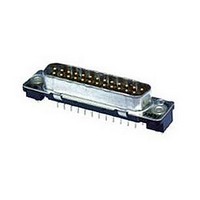
745414-7
Description
Conn D-Subminiature PIN 50 POS 2.76mm Solder ST Thru-Hole 50 Terminal 1 Port
Manufacturer
TE Connectivity
Type
D-Subminiaturer
Specifications of 745414-7
Gender
PIN
Pitch
2.76 mm
Termination Method
Solder
Mounting
Through Hole
Body Orientation
Straight
Peak Reflow Compatible (260 C)
No
Body Material
Steel
Leaded Process Compatible
No
Mounting Type
Through Hole
Contact Plating
Gold
Connector Type
D Sub
Rohs Compliant
No
Pcb Mounting Orientation
Vertical
Product Series
HD 20
Mating Connector Lock
Without
Pcb Mount Retention
Without
Shell Type
Full Metal
Shell Size
5
Grounding Indents
With
Grounding Straps
Without
Pcb Mount Style
Through Hole
Color Code
None
Sealed
No
Profile
High
Post Size (mm [in])
0.64 [.025]
Mounting Hole Diameter (mm [in])
3.05 [.120]
Shell Material
Steel
Panel Mount Retention
Without
Grounding Clips
Without
Termination Post Length (mm [in])
4.78 [0.188]
Solder Tail Contact Plating
Tin-Lead over Nickel
Number Of Positions
50
Pcb Mount Retention Type
Mounting Holes
Insert Flammability Rating
UL 94V-0
Insert Material
Thermoplastic
Shell Plating
Tin
Contact Plating, Mating Area, Material
Gold (30), Gold Flash over Palladium Nickel
Contact Shape
Square
Contact Base Material
Brass
Connector Style
Plug
Rohs/elv Compliance
ELV compliant, 5 of 6 Compliant
Lead Free Solder Processes
Not suitable for lead free processing
Pcb Thickness, Recommended (in [mm])
0.093 – 0.125 [2.36 – 3.18]
Application
Standard
Available stocks
Company
Part Number
Manufacturer
Quantity
Price
Company:

Part Number:
745414-7
Manufacturer:
TE Connectivity AMP Connectors
Quantity:
457


Rev C
Durability.
Mating force.
Unm ating force.
Therm al shock.
Hum idity-tem perature cycling.
Tem perature life.
Mixed flowing gas.
NOTE
Test Description
Shall m eet visual requirem ents, show no physical dam age and shall m eet requirem ents of
additional tests as specified in Test Sequence in Figure 2.
See Note.
Note: Grounding indents are on the
plugs.
Note: Grounding indents are on the
plugs.
See Note.
See Note.
See Note.
See Note.
Size
Size
1
2
3
4
5
1
2
3
4
5
Positions
Positions
ENVIRONMENTAL
Figure 1 (end)
15
25
37
50
15
25
37
50
Requirem ent
9
9
Ground Ground
Indents Indents
Ground Ground
Indents Indents
Lbs Maxim um
Lbs Maxim um
W /O
W /O
12.5
18.5
25.0
12.5
18.5
25.0
4.5
7.5
4.5
7.5
W ith
W ith
30
33
37
40
44
30
33
37
40
44
TE Spec 109-27.
Mate and unm ate assem blies for
100 cycles for gold flash
assem blies and 500 cycles for 30
µin gold plated assem blies at a
m axim um rate of 200 cycles per
hour.
TE Spec 109-42, Condition A.
Measure force necessary to m ate
connector assem blies using free
floating fixtures at a rate of 1 inch
per m inute.
TE Spec 109-42, Condition A.
Measure force necessary to
unm ate connector assem blies at
rate of 1 inch per m inute.
TE Spec 109-22.
Subject m ated connectors to 100
cycles between -55 and 105 C.
TE Spec 109-23-4, Condition B.
Subject m ated connectors to 10
hum idity-tem perature cycles
between 25 and 65 C at 95% RH.
TE Spec 109-43.
Subject m ated connectors to
tem perature life at 105 C for 500
hours.
TE Spec 109-85-3.
Subject m ated connectors to
environm ental class III for 20 days.
Precondition connectors with 10
durability cycles.
Procedure
108-40025
3 of 7
Related parts for 745414-7
Image
Part Number
Description
Manufacturer
Datasheet
Request
R

Part Number:
Description:
Conn D-Subminiature PIN 50 POS 2.76mm Solder ST Thru-Hole 50 Terminal 1 Port
Manufacturer:
TE Connectivity
Datasheet:

Part Number:
Description:
Printers THERMAL PRINTER HS-SLEEVE MARKER
Manufacturer:
TE Connectivity


Part Number:
Description:
High Speed / Modular Connectors 30P HEADER ASSY
Manufacturer:
TE Connectivity
Datasheet:

Part Number:
Description:
High Speed / Modular Connectors REC 6X005P R/A LT B-PLANE HS3
Manufacturer:
TE Connectivity
Datasheet:

Part Number:
Description:
High Speed / Modular Connectors 2MM HM RCPT 50P R/A AU
Manufacturer:
TE Connectivity
Datasheet:

Part Number:
Description:
High Speed / Modular Connectors 2MM HM RCPT 50P R/A AU
Manufacturer:
TE Connectivity
Datasheet:


Part Number:
Description:
Manufacturer:
TE Connectivity
Datasheet:


Part Number:
Description:
Manufacturer:
TE Connectivity
Datasheet:

Part Number:
Description:
Manufacturer:
TE Connectivity
Datasheet:

Part Number:
Description:
Manufacturer:
TE Connectivity
Datasheet: