HEDB-9100-A01 Avago Technologies US Inc., HEDB-9100-A01 Datasheet - Page 2
HEDB-9100-A01
Manufacturer Part Number
HEDB-9100-A01
Description
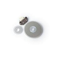
Encoders 2 Channel 500 CPR 2mm Carbon Wheel
Manufacturer
Avago Technologies US Inc.
Datasheet
1.HEDB-9100-A01.pdf
(5 pages)
Specifications of HEDB-9100-A01
Number Of Channels
2
Product
Optical
Pulses Per Revolution
500 CPR
Lead Free Status / RoHS Status
Lead free / RoHS Compliant


Theory of Operation
The HEDB-9100 and 9000 is emitter/detector modules.
Coupled with a codewheel, these modules translate
the rotary motion of a shaft into a two-channel digital
output.
As seen in Figure 1, the modules contain a single Light
Emitting Diode (LED) as its light source. The light is
collimated into a parallel beam by means of a single
polycarbonate lens located directly over the LED.
Opposite the emitter is the integrated detector circuit.
This IC consists of multiple sets of photodetectors and
the signal processing circuitry necessary to produce
the digital waveforms.
The codewheel rotates between the emitter and
detector, causing the light beam to be interrupted by
the pattern of spaces and bars on the codewheel.
The photodiodes which detect these interruptions are
arranged in a pattern that corresponds to the radius
and design of the code-wheel. These detectors are also
spaced such that a light period on one pair of detectors
corresponds to a dark period on the adjacent pair of
detectors.
The photodiode outputs are then fed through the
signal processing circuitry resulting in A, Abar, B, Bbar.
Two comparators receive these signals and produce
the final outputs for channels A and B. Due to this
integrated phasing technique, the digital output of
channel A is in quadrature with that of channel B (90
degrees out of phase).
Definitions
Note: Refer to Figure 2
Count (N): The number of bar and window pairs or
counts per revolution (CPR) of the codewheel.
One Cycle (C): 360 electrical degrees (°e), 1 bar and
window pair.
One Shaft Rotation: 360 mechanical degrees, N cycles.
Position Error (∆Θ
between the actual shaft position and the position
indicated by the encoder cycle count.
2
∆Θ
∆Θ
∆Θ
∆Θ): The normalized angular difference
Cycle Error (∆ ∆ ∆ ∆ ∆ C): An indication of cycle uniformity. The
difference between an observed shaft angle which
gives rise to one electrical cycle, and the nominal
angular increment of 1/N of a revolution.
Pulse Width (P): The number of electrical degrees that
an output is high during 1 cycle. This value is nominally
180°e or 1/2 cycle.
Pulse Width Error (∆ ∆ ∆ ∆ ∆ P): The deviation, in electrical
degrees, of the pulse width from its ideal value of
180°e.
State Width (S): The number of electrical degrees
between a transition in the output of channel A and
the neighboring transition in the output of channel B.
There are 4 states per cycle, each nominally 90°e.
Phase (φ φ φ φ φ ): The number of electrical degrees between
the center of the high state of channel A and the center
of the high state of channel B. This value is nominally
90°e for quadrature output.
Phase Error (φ φ φ φ φ ): The deviation of the phase from its
ideal value of 90°e.
Direction of Rotation: When the codewheel rotates
in the clockwise direction viewing from top of the
module (direction from V to G), channel A will lead
channel B. If the codewheel rotates in the opposite
direction, channel B will lead channel A.
Optical Radius (Rop): The distance from the
codewheel’s center of rotation to the optical center
(O.C) of the encoder module.
Specification
For encoder electrical, mechanical specifications,
codewheel technical specifications and additional
informations pls refer to :
• HEDS-9000 /9100 Datasheet.
• HEDS/HEDG/HEDM – 51xx /61xx Codewheel
Datasheet
Related parts for HEDB-9100-A01
Image
Part Number
Description
Manufacturer
Datasheet
Request
R

Part Number:
Description:
En,3CH,1024CPR,MCW,23ROP,1/2IN,B/L
Manufacturer:
Avago Technologies US Inc.
Datasheet:
Part Number:
Description:
Optoelectronic Miscellaneous, Other
Manufacturer:
Avago Technologies US Inc.
Datasheet:
Part Number:
Description:
Optoelectronic Miscellaneous, Other
Manufacturer:
Avago Technologies US Inc.
Datasheet:
Part Number:
Description:
Optoelectronic Miscellaneous, Other
Manufacturer:
Avago Technologies US Inc.
Datasheet:
Part Number:
Description:
Optoelectronic Miscellaneous, Other
Manufacturer:
Avago Technologies US Inc.
Datasheet:
Part Number:
Description:
Optoelectronic Miscellaneous, Other
Manufacturer:
Avago Technologies US Inc.
Datasheet:
Part Number:
Description:
Optoelectronic Miscellaneous, Other
Manufacturer:
Avago Technologies US Inc.
Datasheet:

Part Number:
Description:
Optoelectronic Miscellaneous, Other
Manufacturer:
Avago Technologies US Inc.
Datasheet:
Part Number:
Description:
Optoelectronic Miscellaneous, Other
Manufacturer:
Avago Technologies US Inc.
Datasheet:
Part Number:
Description:
Optoelectronic Miscellaneous, Other
Manufacturer:
Avago Technologies US Inc.
Datasheet:

Part Number:
Description:
OPTOCOUPLER GATE DRV 2A 16-SOIC
Manufacturer:
Avago Technologies US Inc.
Datasheet:
Part Number:
Description:
OPTOCOUPLER 2CH 2.5A 16-SOIC
Manufacturer:
Avago Technologies US Inc.
Datasheet:

Part Number:
Description:
OPTOCOUPLER GATE DRV 0.4A 16SOIC
Manufacturer:
Avago Technologies US Inc.
Datasheet:

Part Number:
Description:
OPTOCOUPLER 2.0A 250KHZ 8-DIP
Manufacturer:
Avago Technologies US Inc.
Datasheet:

Part Number:
Description:
OPTOCOUPLER 2.0A 250KHZ GW 8-SMD
Manufacturer:
Avago Technologies US Inc.
Datasheet: