HEDS-9711#R50 Avago Technologies US Inc., HEDS-9711#R50 Datasheet - Page 2
HEDS-9711#R50
Manufacturer Part Number
HEDS-9711#R50
Description
Encoders 2 Channel 200CPR
Manufacturer
Avago Technologies US Inc.
Type
Optical Encoderr
Datasheet
1.HEDS-9711R50.pdf
(8 pages)
Specifications of HEDS-9711#R50
Number Of Channels
2
Mounting Style
PCB
Supply Voltage
5 V
Product
Optical
Technology
Linear
Termination Style
Solder Pin
Pulses Per Revolution
900
Detents
No
Motion
Rotary
Index Output
Not Indexed
Encoder Signal
Digital Square Wave
Built In Switch
No
Shaft Style
Hollow
Shaft Diameter (mm)
2mm
Operating Supply Voltage (typ)
5VDC
Operating Temperature Min Deg. C
15C
Operating Temperature Max Deg. C
45C
Terminal Type
PC Pins
Lead Free Status / RoHS Status
Lead free / RoHS Compliant
Available stocks
Company
Part Number
Manufacturer
Quantity
Price


Absolute Maximum Ratings
Recommended Operating Conditions
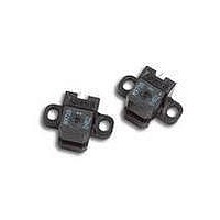
Theory of Operation
The HEDS-9710/HEDS-9711 is a
C-shaped emitter/detector mod-
ule. Coupled with a codewheel, it
translates rotary motion into a
two-channel analog output.
Coupled with a codestrip, it trans-
lates linear motion into analog
outputs.
The module contains a single
Light Emitting Diode (LED) as its
light source. The light is colli-
mated into a parallel beam by
means of a single lens located
directly over the LED. Opposite
the emitter is the integrated de-
tector circuit. This IC consists of
multiple sets of photodetectors
and the signal processing cir-
cuitry necessary to produce the
analog waveforms.
The codewheel/codestrip moves
between the emitter and detector,
causing the light beam to be in-
terrupted by the pattern of spaces
and bars on the codewheel/
codestrip. The photodiodes which
detect these interruptions are
arranged in a pattern that corre-
sponds to the radius and count
density of the codewheel/
codestrip. These detectors are
also spaced such that a light
period on one pair of detectors
corresponds to a dark period on
the adjacent pair of detectors.
2
Parameter
Storage Temperature
Operating Temperature
Supply Voltage
Soldering Temperature
Parameter
Temperature
Supply Voltage
Count Frequency
Symbol
T
V
CC
Symbol
T
T
V
S
A
CC
The photodiode outputs are fed
through the signal processing
circuitry, which produces the final
outputs for channels A and B. Due
to this integrated phasing tech-
nique, the analog output of chan-
nel A is in quadrature with
channel B (90 degrees out of
phase).
Package Dimensions
See HEDS-9700 datasheet for
package outline drawings.
Definitions
Count (N): The number of bar
and window pairs or Counts Per
Revolution (CPR) of the code-
wheel, or the number of Lines Per
Inch (LPI) of the codestrip.
1 Shaft Rotation = 360 mechanical
1 cycle (c) = 360 electrical
Pulse Width (P): The number of
electrical degrees that an output
is high during one cycle. This
value is nominally 180 e or 1/2
cycle.
Pulse Width Error ( P): The
deviation, in electrical degrees, of
the pulse width from its ideal
value of 180 e.
Min.
15
4.8
–40
15
–0.5
Min.
= 1 bar and window pair
degrees ( e)
= N cycles
degrees
Max.
45
5.2
8
Max.
45
7
260
85
Units
V
kHz
State Width (S): The number of
electrical degrees between a
transition in the output of chan-
nel A and the neighboring transi-
tion in the output of channel B.
There are four states per cycle,
each nominally 90 e.
State Width Error ( S): The
deviation, in electrical degrees, of
each state width from its ideal
value of 90 e.
Phase ( ): The number of elec-
trical degrees between the center
of the high state of channel A and
the center of the high state of
channel B. This value is nomi-
nally 90 e for quadrature output.
Phase Error (
tion of the phase from its ideal
value of 90 e.
Direction of Rotation: When
the codewheel rotates counter-
clockwise, as viewed looking
down on the module (so the
marking is visible), channel A will
lead channel B. If the codewheel
rotates in the opposite direction,
channel B will lead channel A.
Optical Radius (R
distance from the codewheel’s
center of rotation to the optical
center (O.C.) of the encoder
module.
Mounting Position (R
Distance from Motor Shaft center
of rotation to center of Alignment
Tab receiving hole.
Units
V
C
C
C
Notes
Ripple < 100 mV
(Velocity (rpm) x N) 60
): The devia-
Notes
t 5 sec.
OP
): The
M
):
p-p
Related parts for HEDS-9711#R50
Image
Part Number
Description
Manufacturer
Datasheet
Request
R

Part Number:
Description:
ENCODER OPTICAL GAP 3CH 500CPR
Manufacturer:
Avago Technologies US Inc.
Datasheet:

Part Number:
Description:
Encoders 2 Channel 256CPR
Manufacturer:
Avago Technologies US Inc.
Datasheet:
Part Number:
Description:
Encoders 2 Channel 150CPR
Manufacturer:
Avago Technologies US Inc.
Datasheet:
Part Number:
Description:
Encoders 2 Channel 120CPR
Manufacturer:
Avago Technologies US Inc.
Datasheet:
Part Number:
Description:
SML ENC MOD 2CH BENT LDS 100 CPR
Manufacturer:
Avago Technologies US Inc.
Datasheet:
Part Number:
Description:
Encoders 2 Channel 400CPR
Manufacturer:
Avago Technologies US Inc.
Datasheet:

Part Number:
Description:
Encoders 2 Channel 180CPR
Manufacturer:
Avago Technologies US Inc.
Datasheet:
Part Number:
Description:
Encoders 2 Channel 400CPR
Manufacturer:
Avago Technologies US Inc.
Datasheet:
Part Number:
Description:
Encoders 2 Channel 150CPR
Manufacturer:
Avago Technologies US Inc.
Datasheet:
Part Number:
Description:
Encoders 2 Channel 150CPR
Manufacturer:
Avago Technologies US Inc.
Datasheet:
Part Number:
Description:
Encoders 2 Channel 150CPR
Manufacturer:
Avago Technologies US Inc.
Datasheet:
Part Number:
Description:
Encoders 2 Channel 150CPR
Manufacturer:
Avago Technologies US Inc.
Datasheet:
Part Number:
Description:
Encoders 2 Channel 360CPR
Manufacturer:
Avago Technologies US Inc.
Datasheet:
Part Number:
Description:
Encoders 2 Channel 150CPR
Manufacturer:
Avago Technologies US Inc.
Datasheet:
Part Number:
Description:
Encoders 2 Channel 400CPR
Manufacturer:
Avago Technologies US Inc.
Datasheet: