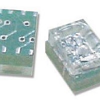
HEDR-5120#H12 Avago Technologies US Inc., HEDR-5120#H12 Datasheet - Page 5

HEDR-5120#H12
Manufacturer Part Number
HEDR-5120#H12
Description
Encoders 2 Channel 408CPR
Manufacturer
Avago Technologies US Inc.
Type
Optical Encoderr
Datasheet
1.HEDR-5120H12.pdf
(8 pages)
Specifications of HEDR-5120#H12
Number Of Channels
2
Product
Optical
Size / Dimension
6 mm
Pulses Per Revolution
400 CPR
Detents
No
Motion
Rotary
Mounting Style
Surface Mount
Index Output
Not Indexed
Encoder Signal
Digital Square Wave
Built In Switch
No
Shaft Style
Hollow
Shaft Diameter (mm)
6mm
Operating Supply Voltage (typ)
5VDC
Operating Temperature Min Deg. C
-10C
Operating Temperature Max Deg. C
85C
Terminal Type
Gull Wing
Lead Free Status / RoHS Status
Lead free / RoHS Compliant
Electrical Interface
To ensure reliable encoding
performance, the HEDR-5300
encoder requires 2.7 k
pull-up resistors on output pins 2
and 4 (Channels A and B) as
shown in Figure 1. These pull-up
Encoding Characteristics
Encoding Characteristics over the Recommended Operating Conditions and Mounting Conditions.
Electrical Characteristics
Electrical Characteristics over the Recommended Operating Conditions. Typical Values at 25 C
and V
5
Figure 1. Pull-up Resistors on HEDR-5300 Encoder Outputs.
Supply Current
High Level Output Voltage
Low Level Output Voltage
Rise Time
Fall Time
Pulse Width Error
State Width Error
Phase Error
Position Error
Cycle Error
CC
Parameter
Parameter
= 5 V.
(
10%)
Symbol
Symbol Min.
P
C
S
ø
V
V
I
4
3
2
1
+5 V
t
CC
t
OH
OL
r
f
resistors should be located as
close to the encoder as possible
(within 4 feet). Each of the
encoder outputs can drive a
single TTL load in this
configuration.
GND
2.4
Typ.
15
15
25
10
8
R
R = 2.7 K
Typ.
150
18
50
R
Max.
120
75
60
60
75
Max.
200
0.4
60
arc min.
Units
e
e
e
e
CHANNEL B
CHANNEL A
Units
Volts
Volts
mA
ns
ns
TO OUTPUT LOGIC
(ONE TTL LOAD
PER OUTPUT)
I
OH
I
OL
R
C
= - 40 A min.
L
L
= 3.86 mA
Notes
= 2.7 k
= 25 pF


