583853-9 TE Connectivity, 583853-9 Datasheet - Page 25
583853-9
Manufacturer Part Number
583853-9
Description
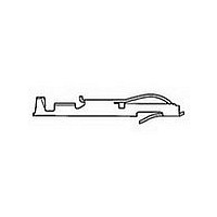
Conn Bifurcated Contact SKT 1 POS Crimp ST Cable Mount Loose Piece
Manufacturer
TE Connectivity
Type
Bifurcated Contactr
Specifications of 583853-9
Number Of Contacts
1
Contact Plating
Gold Over Nickel
Mounting
Cable Mount
Termination Method
Crimp
Body Orientation
Straight
Contact Material
Phosphor Bronze
Mounting Style
Cable
Operating Temp Range
-55C to 105C
Pitch (mm)
Not Requiredmm
Current Rating (max)
5A
Contact Resistance Max
10
Rohs Compliant
YES
Product Type
Contact
Termination Method To Wire/cable
Crimp
Wire Insulation Diameter (mm [in])
1.22 – 1.52 [0.048 – 0.060]
Color Code
Green
Contact Retention In Housing
Crimp Snap-In
Solder Tail Contact Plating
Gold Flash over Nickel (30)
Centerline (mm [in])
2.54 [0.100], 3.18 [0.125], 3.96 [0.156]
Wire Range (mm [awg])
0.20-0.60² [24-20]
Contact Configuration
Bifurcated
Contact Plating, Mating Area, Material
Gold (50)
Contact Base Material
Phosphor Bronze
Rohs/elv Compliance
RoHS compliant, ELV compliant
Lead Free Solder Processes
Not relevant for lead free process
Rohs/elv Compliance History
Always was RoHS compliant
Contact Packaging Method
Loose Piece
Lead Free Status / RoHS Status
Compliant


86
Housings
(Hermaphroditic),
24 Positions
Material
Housing — Glass-filled polybutylene
terephthalate (PBT), blue
Bushing — Brass, zinc-plated
Related Product Data
Performance Specifications —
page 85
MIC Contacts — page 87
Crimp Snap-In Contacts — page 87
Technical Documents
Product Specification
108-5371
Catalog 1773096
Revised 2-10
www.tycoelectronics.com
Recommended Panel Cutout
Dimensions are in inches and
millimeters unless otherwise
specified. Values in brackets
are metric equivalents.
Power Connectors & Interconnection Systems
Hybrid Blind-Mate Drawer Connectors
Note: All part numbers are RoHS compliant.
[11.22]
[11.80]
.441
.440
[5.00]
.197
[70.00]
2.756
[45.00]
[60.80]
1.771
2.394
Pitch
Dimensions are shown for
reference purposes only.
Specifications subject
to change.
Signal Circuits
Upward and downward = Axial clearance
Circumferential = Floating
Up- and downward = 0.05 [.002]
Up- and downward = 0.30 [.012]
*Dimensions applicable for rear mounting.
[12.22]
[12.18]
Circumferential = 0.14 [.006]
Circumferential = 0.80 [.031]
.481
.480
Floating of Bushing
[5.00]
.197*
[6.10]
0.24
[30.00]
Power Circuits
1.181
[17.9]
0.70
(4 corners)
.197*
[5.00]
[29.1]
1.15
[72.00]
[60.80]
[54.80]
[49.60]
2.835
2.394
USA: 1-800-522-6752
Canada: 1-905-470-4425
Mexico: 01-800-733-8926
C. America: 52-55-1106-0803
2.157
1.953
[2.50]
.098
(Continued)
R*
Note: Reverse figures show circuit numbers.
(Example =
B13
A1
A13
B1
Panel Mounting Position
All Corners
Part Numbers
[3.300]
.130
5176916-1
5176916-2
(Front Mounting)
Housing
R1
Dia.
[32.00]
1.260
B14
A2
used for No. 13 on the reverse side.)
[9.60]
B13
A14
A1
.378
B2
South America: 55-11-2103-6000
Hong Kong: 852-2735-1628
Japan: 81-44-844-8013
UK: 44-(0)8002-67666
The hole used for No. 1 circuit is
A23
B11
A11
B23
Related parts for 583853-9
Image
Part Number
Description
Manufacturer
Datasheet
Request
R


Part Number:
Description:
CONTACT, SOCKET, 24-20AWG, CRIMP
Manufacturer:
TE Connectivity
Datasheet:
Part Number:
Description:
TWIN LEAF TERMINAL STRIP
Manufacturer:
TE Connectivity
Datasheet:
Part Number:
Description:
Conn Bifurcated Contact SKT 1 POS Crimp ST Cable Mount Loose Piece
Manufacturer:
TE Connectivity
Datasheet:

Part Number:
Description:
High Speed / Modular Connectors 30P HEADER ASSY
Manufacturer:
TE Connectivity
Datasheet:

Part Number:
Description:
High Speed / Modular Connectors REC 6X005P R/A LT B-PLANE HS3
Manufacturer:
TE Connectivity
Datasheet:

Part Number:
Description:
High Speed / Modular Connectors 2MM HM RCPT 50P R/A AU
Manufacturer:
TE Connectivity
Datasheet:

Part Number:
Description:
High Speed / Modular Connectors 2MM HM RCPT 50P R/A AU
Manufacturer:
TE Connectivity
Datasheet:


Part Number:
Description:
Manufacturer:
TE Connectivity
Datasheet:


Part Number:
Description:
Manufacturer:
TE Connectivity
Datasheet:

Part Number:
Description:
Manufacturer:
TE Connectivity
Datasheet:

Part Number:
Description:
Manufacturer:
TE Connectivity
Datasheet: