5536504-2 TE Connectivity, 5536504-2 Datasheet - Page 9
5536504-2
Manufacturer Part Number
5536504-2
Description
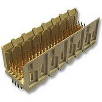
Conn Backplane PIN 48 POS 2mm Press Fit ST Thru-Hole
Manufacturer
TE Connectivity
Type
Backplaner
Series
Z-PACKr
Specifications of 5536504-2
Pitch
2 mm
Number Of Rows
4
Number Of Contacts
48
Termination Method
Press Fit
Mounting
Through Hole
Contact Plating
Gold Over Nickel
Pitch (mm)
2mm
Gender
Pin
Body Orientation
Straight
Number Of Contact Rows
4
Mounting Style
Through Hole
Voltage Rating Max
30VAC
Contact Material
Phosphor Bronze
Housing Color
Natural
Housing Material
Liquid Cryst Polymer
Product Height (mm)
17mm
Product Depth (mm)
15.8mm
Product Length (mm)
23.88mm
Connector Type
Backplane
Row Pitch
2mm
Pitch Spacing
2mm
No. Of Contacts
48
Contact Termination
Press Fit
No. Of Rows
4
Contact
RoHS Compliant
Number Of Positions / Contacts
48
Mounting Angle
Vertical
Termination Style
Pin
Product Type
Connector
Pcb Mounting Orientation
Vertical
Post Type
Press-Fit
Module Type
Signal
Mating Post Length (mm [in])
6.50 [0.256]
Press-fit Post Style
Compliant Pin
Pin Header Width (mm [in])
16.00 [0.622]
Voltage Rating (vac)
30
Termination Post Length (mm [in])
4.25 [0.167]
Number Of Signal Positions
48
Sequencing
No
Post Plating
Tin
Centerline, Matrix (mm [in])
2.00 x 2.00 [.079 x .079]
Contact Type
Pin
Contact Base Material
Phosphor Bronze
Contact Plating, Mating Area, Material
Gold (30)
Connector Style
Plug
Rohs/elv Compliance
RoHS compliant, ELV compliant
Lead Free Solder Processes
Not relevant for lead free process
Rohs/elv Compliance History
Always was RoHS compliant
Applies To
Printed Circuit Board
Application
Fixed-Board
Lead Free Status / RoHS Status
Compliant
Lead Free Status / RoHS Status
Compliant


3.6. Special Handling
Rev E
0.004--0.010
0.0005--0.004
0.0002--0.0005
0.0001--0.0005 Au,
0.00127--0.0076 Ni
0.0001--0.0005
C. Contact Hole Configuration
The contact holes in the pc board for all connectors must be prepared to the dimensions specified in
Figure 7.
THICKNESS
A. Initial Positioning
Prior to positioning a connector, the pc board should be placed on an appropriate board support fixture.
Connectors should be gripped by the housing only and not by the contacts. When placing a connector into
4- - ROW
264
240
216
192
168
144
120
------
96
72
48
24
NUMBER OF SIGNAL POSITIONS
0.65- - 0.80 (Ref)
Diameter of Finished
Hole After Plating
Hot Air Solder Leveling (HASL) Tin--Lead (Sn Pb)
Immersion Tin (Sn)
Organic Solderability Preservative (OSP)
Immersion Gold (Au) Over Nickel (Ni) (ENIG)
Immersion Silver (Ag)
0.81- - 0.86
Drilled Hole
Diameter
5- - ROW
630
540
330
300
270
240
210
180
150
120
90
60
30
SURFACE FINISH
Figure 6 (end)
Figure 7
PLATING
DIMENSION B
DIMENSION B
125
107
65
59
53
47
41
35
29
23
17
11
5
Surface Finish (See Table Below)
PC Board Thickness
(See Paragraph 3.5)
1.12 Min
Pad Diameter
0.025- - 0.050
Copper Plating
FR- - 4
Material
DIMENSION C
DIMENSION C
250
214
130
106
118
94
82
70
58
46
34
22
10
114- 1075
9 of 15
Related parts for 5536504-2
Image
Part Number
Description
Manufacturer
Datasheet
Request
R

Part Number:
Description:
Printers THERMAL PRINTER HS-SLEEVE MARKER
Manufacturer:
TE Connectivity


Part Number:
Description:
High Speed / Modular Connectors 30P HEADER ASSY
Manufacturer:
TE Connectivity
Datasheet:

Part Number:
Description:
High Speed / Modular Connectors REC 6X005P R/A LT B-PLANE HS3
Manufacturer:
TE Connectivity
Datasheet:

Part Number:
Description:
High Speed / Modular Connectors 2MM HM RCPT 50P R/A AU
Manufacturer:
TE Connectivity
Datasheet:

Part Number:
Description:
High Speed / Modular Connectors 2MM HM RCPT 50P R/A AU
Manufacturer:
TE Connectivity
Datasheet:


Part Number:
Description:
Manufacturer:
TE Connectivity
Datasheet:


Part Number:
Description:
Manufacturer:
TE Connectivity
Datasheet:

Part Number:
Description:
Manufacturer:
TE Connectivity
Datasheet:

Part Number:
Description:
Manufacturer:
TE Connectivity
Datasheet: