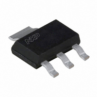
BT134W-600,135 NXP Semiconductors, BT134W-600,135 Datasheet - Page 4

BT134W-600,135
Manufacturer Part Number
BT134W-600,135
Description
TRIAC 600V 1A 35MA SOT223
Manufacturer
NXP Semiconductors
Type
TRIACr
Specifications of BT134W-600,135
Package / Case
TO-261-4, TO-261AA
Triac Type
Standard
Mounting Type
Surface Mount
Configuration
Single
Current - Hold (ih) (max)
15mA
Voltage - Off State
600V
Current - Gate Trigger (igt) (max)
35mA
Current - Non Rep. Surge 50, 60hz (itsm)
10A, 11A
Current - On State (it (rms)) (max)
1A
Voltage - Gate Trigger (vgt) (max)
1.5V
Current - On State (it (rms) (max)
1A
Rated Repetitive Off-state Voltage Vdrm
600 V
Breakover Current Ibo Max
11 A
Off-state Leakage Current @ Vdrm Idrm
0.5 mA
Gate Trigger Voltage (vgt)
1.5 V
Gate Trigger Current (igt)
70 mA
Holding Current (ih Max)
15 mA
Forward Voltage Drop
1.5 V @ 2 A
Mounting Style
SMD/SMT
Repetitive Peak Forward Blocking Voltage
600 V
Repetitive Peak Off-state Volt
600V
Off-state Voltage
600V
Hold Current
15mA
Gate Trigger Current (max)
70mA
Gate Trigger Voltage (max)
1.5V
Package Type
SOT-223
Peak Repeat Off Current
500uA
Peak Surge On-state Current (max)
11A
On State Voltage(max)
1.5@2AV
Mounting
Surface Mount
Pin Count
3 +Tab
Operating Temp Range
-40C to 125C
Operating Temperature Classification
Automotive
Lead Free Status / RoHS Status
Lead free / RoHS Compliant
Lead Free Status / RoHS Status
Lead free / RoHS Compliant, Lead free / RoHS Compliant
Other names
568-1774-2
934000960135
BT134W-600 /T3
934000960135
BT134W-600 /T3
Philips Semiconductors
September 1997
Triacs
Fig.8. Normalised latching current I
Fig.9. Normalised holding current I
2.5
1.5
0.5
2.5
1.5
0.5
I
GT
3
2
1
0
2.5
1.5
0.5
3
2
1
0
-50
-50
(T
3
2
1
0
IGT(25 C)
IL(25 C)
-50
IGT(Tj)
IL(Tj)
IH(25C)
IH(Tj)
Fig.7. Normalised gate trigger current
j
)/ I
GT
versus junction temperature T
versus junction temperature T
(25˚C), versus junction temperature T
0
0
0
BT136
TRIAC
TRIAC
Tj / C
Tj / C
Tj / C
50
50
50
100
T2+ G-
T2- G-
100
100
T2+ G+
T2- G+
H
L
(T
(T
j
j
)/ I
)/ I
j
j
.
.
H
L
(25˚C),
(25˚C),
150
150
150
j
.
4
Fig.10. Typical and maximum on-state characteristic.
temperature, parameter commutation dI
should commutate when the dV/dt is below the value
on the appropriate curve for pre-commutation dI
Fig.11. Transient thermal impedance Z
Fig.12. Typical commutation dV/dt versus junction
1000
100
1.5
0.5
0.01
10
100
2
1
0
0.1
1
10
0
1
10us
0
IT / A
dVcom/dt (V/us)
Tj = 125 C
Tj = 25 C
Vo = 1.0 V
Rs = 0.21 Ohms
Zth j-sp (K/W)
dIcom/dt = 5.1
0.1ms
0.5
A/ms
pulse width t
1ms
unidirectional
50
3.9
BT134W
typ
tp / s
Tj / C
VT / V
10ms
BT134W
3
1
P
D
2.3
bidirectional
BT134W series
p
0.1s
.
100
Product specification
1.8
t
p
max
off-state dV/dt limit
1.5
BT134...G SERIES
BT134...F SERIES
1.4
BT134 SERIES
T
1s
th j-sp
/dt. The triac
t
, versus
Rev 1.200
10s
150
2
T
/dt.


