201389-1 TE Connectivity, 201389-1 Datasheet - Page 7
201389-1
Manufacturer Part Number
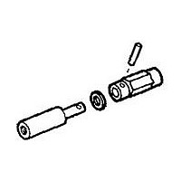
201389-1
Description
Connector Accessories Female Jackscrew Zinc Alloy Clear Chromate Finish Loose Piece
Manufacturer
TE Connectivity
Type
Jackscrewr
Series
Mr
Datasheet
1.201389-1.pdf
(100 pages)
Specifications of 201389-1
Product Length (mm)
30.48mm
Product Depth (mm)
4.75mm
Accessory Type
JACK SCREW
Product Type
Hardware
Gender
Female
Jackscrew Type
Turnable
Jackscrew Material
Zinc Alloy
Thread Size
6-32 [M3.5 x 0.6] Double Thread, Double Lead
Hardware Type
Jackscrew
Mounting Hardware
None
Jackscrew Style
Short-Short
Thread Lead Type
Double
Jackscrew Coating
Clear Chromate
Jackscrew Tip, Roll Pin Material
Stainless Steel
Used With
Standard Connectors
Rohs/elv Compliance
RoHS compliant, ELV compliant
Lead Free Solder Processes
Not relevant for lead free process
Rohs/elv Compliance History
Always was RoHS compliant
Packaging Method
Loose Piece
Lead Free Status / RoHS Status
Compliant


The total current capacity of
each contact in a given con-
nector is dependent upon the
heat rise resulting from the
combination of electrical
loads of the contacts in the
connector arrangement and
the maximum ambient tem-
perature in which the
connector will be operating.
Caution must be taken to
ensure that this combination
of conditions does not cause
the internal temperature of
the connector to exceed the
maximum operating temper-
ature of the housing material.
Several variables which must
be considered when deter-
mining this maximum current
capability for your applica-
tion are:
Current Rating Verification
Can a contact rated at 10
amps carry 10 amps?
Maybe yes, but probably not.
The reason lies in the test
conditions used to rate the
contact. If these conditions
do not adequately reflect the
application conditions, the
actual allowable current lev-
els may be lower than
specified levels. For example,
many manufacturers, includ-
ing Tyco, test a single contact
in air. This gives an accurate
measure of the basic current-
carrying capacity of the
contact. Use the contact
alone in air and it can cer-
tainly carry 10 amperes. Use
it in a multi-position connec-
tor surrounded by other
current-carrying contacts or
in high ambient temperatures,
and the contact should carry
less current.
Similarly, as the contact ages
and stress relaxation, environ-
mental cycling, and other
degradation factors take their
toll, the contact’s current-
carrying capacity decreases.
A prudent design must set
current levels for such end-of-
design-life (EODL) conditions.
Catalog 82003
Revised 06-08
www.tycoelectronics.com
Wire Size - Larger wire will
carry more current since it
has less internal resistance
to current flow and gener-
ates less heat. The wire also
conducts heat away from
the connector.
Dimensions are in millimeters
and inches unless otherwise
specified. Values in brackets are
equivalent U.S. Customary Units.
Contract Carrying Capabilities
AMP M Series
Pin and Socket Connectors
60
Practical current-carrying
capacity is not an absolute,
but an application-dependent
condition.
New Method Simplifies
Ratings
To help the designer set the
appropriate current level,
Tyco has developed a
method of specifying cur-
rent-carrying capacity. This
method takes into account
the various application fac-
tors that influence current
rating.
The method can be summa-
rized as follows:
45
30
75
15
0
The contact is aged to
EODL conditions by durabil-
ity cycling, thermal cycling,
and environmental expo-
sure.
The contact’s resistance
stability is verified.
The current necessary to
produce the specified tem-
perature rise is measured.
This T-rise is usually 30°C.
A rating factor is deter-
mined to allow derating of
multiple contacts in the
same housing and for differ-
ent conductor sizes.
Connector Size - In general,
with more circuits in a con-
nector, less current per
contact can be carried.
CONTACT CURRENT GUIDE Maximum Current (Amperes)
60
56
Dimensions are shown for
reference purposes only.
Specifications subject
to change.
50
45
Temperature
One other factor influencing
current levels is the maximum
operating temperature, for
example, 105°C. If the appli-
cation has a high ambient
temperature (over 75°C) the
contact’s T-rise is limited by
the maximum operating tem-
perature. For example, an
application temperature of
90°C limits the contact T-rise
to 15°C. Since current pro-
duces heat (the I 2 R law), the
current must be lowered to
limit the T-rise.
A contact’s T-rise depends
not only on its I 2 R Joule heat-
ing, but also on its ability to
dissipate the heat. Consider a
contact in a multi-contact
housing. Joule heating in
multiple contacts will raise
the local ambient tempera-
ture. Since the contact will
not be able to dissipate its
own heat as well by convec-
tion, the maximum T-rise will
be realized at a lower current
level. Conse-quently, the
allowable current level must
be lower to maintain an
acceptable T-rise.
For a given connector, the
current level will be set by the
loading density. A connector
35
Current Load Distribution -
Spreading those lines with
greater current loads
through-out the connector,
particularly around the
outer perimeter, will
enhance heat dissipation.
23
USA: 1-800-522-6752
Canada: 1-905-470-4425
Mexico: 01-800-733-8926
C. America: 52-55-5-729-0425
13
NOTE: All part numbers
are RoHS Compliant
11.85
7.5
containing 50% current-carry-
ing contacts will permit higher
currents (per contact) than a
connector will at 75% loading.
The loading percentage
assumes an even distribution
of contacts within the housing.
If all 10 contacts are grouped
together in one section of a
20-position
connector, the loading density
may approach 100%.
The Importance of EODL
As stated, T-rise in a contact
depends on both resistance
and current. As it ages, a con-
tact’s resistance will increase.
The contact designer will
specify a maximum resistance
for the contact, this level is the
end-of-design-life resistance.
Before the contact is tested
for current, Tyco subjects it to
a sequence of tests that exer-
cises the major failure
mechanisms and thereby sim-
ulates EODL conditions.
Conditioning includes mating
cycling, industrial mixed-flow-
ing gases, humidity and
tempera-ture cycling, and
vibration to sequentially
introduce wear, corrosion,
stress relaxation, and
mechanical disturbance.
Ambient Temperature -
With higher ambient
temperatures, less current
can be carried.
South America: 55-11-3611-1514
Hong Kong: 852-2735-1628
Japan: 81-44-844-8013
UK: 44-141-810-8967
Type XII Upgrade
Size 8 Upgrade
.125 POWERBAND
Contact
Size 8
Type XII
Type I, Type II/III +
Upgrade
Type III + , Type II,
Type III + Posted
Size 20 Upgrade
20 DF
7
Related parts for 201389-1
Image
Part Number
Description
Manufacturer
Datasheet
Request
R

Part Number:
Description:
Printers THERMAL PRINTER HS-SLEEVE MARKER
Manufacturer:
TE Connectivity


Part Number:
Description:
Manufacturer:
TE Connectivity
Datasheet:


Part Number:
Description:
Manufacturer:
TE Connectivity
Datasheet:

Part Number:
Description:
Manufacturer:
TE Connectivity
Datasheet:

Part Number:
Description:
Manufacturer:
TE Connectivity
Datasheet:


Part Number:
Description:
Manufacturer:
TE Connectivity
Datasheet:

Part Number:
Description:
Manufacturer:
TE Connectivity
Datasheet: