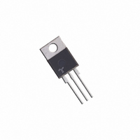
Q6012LH5 Littelfuse / Teccor Brand Thyristors, Q6012LH5 Datasheet - Page 3

Q6012LH5
Manufacturer Part Number
Q6012LH5
Description
ALTERNISTOR 600V 12AMP TO-220AB
Manufacturer
Littelfuse / Teccor Brand Thyristors
Datasheet
1.Q6012LH5.pdf
(8 pages)
Specifications of Q6012LH5
Triac Type
Alternistor - Snubberless
Mounting Type
Through Hole
Configuration
Single
Current - Hold (ih) (max)
50mA
Voltage - Off State
600V
Current - Gate Trigger (igt) (max)
50mA
Current - Non Rep. Surge 50, 60hz (itsm)
110A, 120A
Current - On State (it (rms)) (max)
12A
Voltage - Gate Trigger (vgt) (max)
1.3V
Package / Case
TO-220-3 Isolated Tab
Current - On State (it (rms) (max)
12A
Lead Free Status / RoHS Status
Lead free / RoHS Compliant
Available stocks
Company
Part Number
Manufacturer
Quantity
Price
Company:
Part Number:
Q6012LH5
Manufacturer:
TECCORELE
Quantity:
3 975
Qxx12xHx Series
Note: Alternistors will not operate in QIV
Figure 1: Definition of Quadrants
Figure 3: Normalized DC Holding Current
Figure 5: Power Dissipation (Typical)
4.0
3.0
2.0
1.0
0.0
14
12
10
I
8
6
4
2
0
G T
-65
0
(
(
-
-
-
)
CURRENT WAVEFORM: Sinusoidal
LOAD: Resistive or Inductive
CONDUCTION ANGLE: 360°
)
vs. Junction Temperature
vs. RMS On-State Current
I
GATE
I
GATE
G T
G T
-40
ALL POLARITIES ARE REFERENCED TO MT1
2
REF
12 Amp Alternistor (High Communitation) Triacs
REF
MT2
MT2
-15
RMS On-State Current [I
MT1
MT1
4
Junction Temperature (T
(Negative Half Cycle)
(Positive Half Cycle)
MT2 NEGATIVE
MT2 POSITIVE
QIII
10
QII
6
+
-
QI
QIV
35
(+)
(+)
Teccor
I
GATE
8
I
GATE
G T
G T
T(RMS)
60
J
] -- Amps
) - ºC
10
Revised: November 1, 2010 05:04 PM
REF
MT2
REF
MT2
®
MT1
MT1
85
brand Thyristors
+
12
I
G T
110
101
+125
14
Figure 2: Normalized DC Gate Trigger Current for
Figure 4: Normalized DC Gate Trigger Voltage for
Figure 6: Maximum Allowable Case Temperature
4.0
3.0
2.0
1.0
0.0
2.0
1.5
1.0
0.5
0.0
130
120
110
100
-65
90
80
70
60
-65
Please refer to http://www.littelfuse.com for current information.
0
All Quadrants vs. Junction Temperature
All Quadrants vs. Junction Temperature
vs. On-State Current
CURRENT WAVEFORM: Sinusoidal
LOAD: Resistive or Inductive
CONDUCTION ANGLE: 360°
-40
-40
2
Specifications are subject to change without notice.
-15
-15
RMS On-State Current [I
4
Junction Temperature (T
Junction Temperature (T
Qxx12LH5
10
10
6
35
35
Qxx12RH5
Qxx12NH5
8
T(RMS)
60
©2010 Littelfuse, Inc
60
J
] - Amps
) - C
J
) - ºC
10
85
85
12
110
110
+125
125
14


