213300-1 TE Connectivity, 213300-1 Datasheet - Page 80
213300-1
Manufacturer Part Number
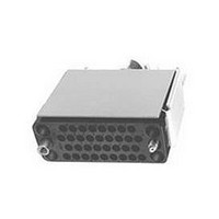
213300-1
Description
Connector Accessories Cable Connector Kit 34 POS Phenolic Black Loose Piece
Manufacturer
TE Connectivity
Type
Kitr
Series
M Seriesr
Datasheet
1.1-200867-1.pdf
(100 pages)
Specifications of 213300-1
Gender
Plug
No. Of Contacts
34
No. Of Rows
4
Contact Gender
Pin
Connector Mounting
Cable
Contact Termination
Screw
Body Material
Phenolic
Rohs Compliant
Yes
Product Type
Housing Kit
Type Of Connector
V.35
Mount
Panel
Jackscrew Type
Turnable
Mount Angle
Vertical
Jackscrew Material
Stainless Steel
Shield Material
Anodized Aluminum
Hardware Type
Jackscrew
Mounting Hardware
None
Shield Style
One-piece
Mounting Screw Material
Steel
Mounting Screw Plating
Zinc
High Voltage
No
Number Of Positions
34
Pin Hood
Without
Jackscrew Style
One-Piece
Preloaded Contacts
No
Mounting Bracket(s)
Without
Shield Size
Short
Cable Diameter Range (mm [in])
11.05 – 13.83 [0.435 – 0.545]
Cable Clamp Material
Steel
Cable Clamp Plating
Nickel
Housing Material
Phenolic - GF
Connector Style
Plug
Housing Color
Black
Rohs/elv Compliance
RoHS compliant, ELV compliant
Lead Free Solder Processes
Not relevant for lead free process
Rohs/elv Compliance History
Always was RoHS compliant
Packaging Method
Loose Piece


80
* A dimension also applies to
other comparably sized con-
nector types listed in the chart
at the right.
Locking Springs
Material and Finish
Male (Spring Member) -
Spring steel, nickel plated
Female (Latching Member) -
Stainless steel
Locking Springs are used
to hold mated connectors
together. Although Locking
Springs can be used on con-
nectors up to 50 positions,
they are primarily used on
smaller size connectors (less
than 34 positions).
In all applications, a Male
(Spring Member) is used
opposite a Female (Latching
Member). They can be secured
to a connector housing using
Guide Pins and Sockets or
4-40 x .250 [6.35] fillister
head screws and nuts. Locking
Springs can be used with all
hardware, except Closed-End
Pin Hoods.
Catalog 82003
Revised 06-08
www.tycoelectronics.com
Connector
Standard
Size*
20
26
34
50
14
41
6
3.047
3.006
35.89
2.037
76.35
1.662
1.975
2.412
77.39
Max.
1.413
42.21
50.17
51.74
61.26
A
Dimensions are in millimeters
and inches unless otherwise
specified. Values in brackets are
equivalent U.S. Customary Units.
*Single female latch, two must be ordered per assembly.
AMP M Series
Pin and Socket Connectors
Fastening Hardware
For Housings with
Single Mounting Hole
For Housings with
Three Mounting Holes
(Assembled)
Member)
Locking Spring Part No.
201923-1
201925-1
201921-1
(Spring
A Max.
Male
(Assembled)
A Max.
[9.53]
.375
Female
(Latching
[9.53]
Member)
.375
201922-1
201918-1*
201926-1
Female
Female
Dimensions are shown for USA: 1-800-522-6752
reference purposes only.
Specifications subject
to change.
[8.13]
.320
(Continued)
34 and 50
Standard
6, 14, 20
[8.13]
and 41
.320
26
Canada: 1-905-470-4425
Mexico: 01-800-733-8926
C. America: 52-55-5-729-0425 UK: 44-141-810-8967
Connectors Used On (No. of Positions)
34 and 50
NOTE: All part numbers
are RoHS Compliant
6, 14, 20
Posted
and 41
26
[9.53]
.375
[9.53]
.375
Current
High
[15.75]
[15.75]
—
—
—
.620
.620
Special Application
South America: 55-11-3611-1514
Hong Kong: 852-2735-1628
Japan: 81-44-844-8013
Male
Male
16 and 42
Mixed
(Assembled)
—
15
(Assembled)
A Max.
A Max.
Voltage
High
20
—
—
Related parts for 213300-1
Image
Part Number
Description
Manufacturer
Datasheet
Request
R

Part Number:
Description:
34 PASSM KIT,M SER (CC,JS)
Manufacturer:
TE Connectivity
Datasheet:

Part Number:
Description:
Printers THERMAL PRINTER HS-SLEEVE MARKER
Manufacturer:
TE Connectivity


Part Number:
Description:
High Speed / Modular Connectors 30P HEADER ASSY
Manufacturer:
TE Connectivity
Datasheet:

Part Number:
Description:
High Speed / Modular Connectors REC 6X005P R/A LT B-PLANE HS3
Manufacturer:
TE Connectivity
Datasheet:

Part Number:
Description:
High Speed / Modular Connectors 2MM HM RCPT 50P R/A AU
Manufacturer:
TE Connectivity
Datasheet:

Part Number:
Description:
High Speed / Modular Connectors 2MM HM RCPT 50P R/A AU
Manufacturer:
TE Connectivity
Datasheet:


Part Number:
Description:
Manufacturer:
TE Connectivity
Datasheet:


Part Number:
Description:
Manufacturer:
TE Connectivity
Datasheet:

Part Number:
Description:
Manufacturer:
TE Connectivity
Datasheet:

Part Number:
Description:
Manufacturer:
TE Connectivity
Datasheet: