RCA060331K6FKEA Vishay, RCA060331K6FKEA Datasheet
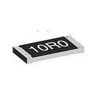
RCA0603 31K6 1% 100 ET1 E3

RCA060331K6FKEA

Manufacturer Part Number
RCA060331K6FKEA
Description
RCA0603 31K6 1% 100 ET1 E3
Manufacturer
Vishay
Type
Thick Filmr
Datasheet

Specifications of RCA060331K6FKEA

Power Rating(s)
1/10W
Resistance
31.6kohm
Tolerance (+ Or -)
1%
Temperature Coefficient
±100
Mounting Style
Surface Mount
Package / Case
0603
Operating Temp Range
-55C to 155C
Case Style
Molded
Military Standard
Not Required
Failure Rate
Not Required
Product Length (mm)
1.55mm
Product Depth (mm)
0.85mm
Product Height (mm)
0.45mm
Lead Free Status / RoHS Status
Compliant
Notes
• These resistors do not feature a limited lifetime when operated within the permissible limits. However, resistance value drift increasing over
• Marking: See document “Surface Mount Resistor Marking” (document number 20020).
• Power rating depends on the max. temperature at the solder point, the component placement density and the substrate material.
Document Number: 20037
Revision: 08-Jul-10
STANDARD ELECTRICAL SPECIFICATIONS
MODEL
RCA0402
RCA0603
RCA0805
RCA1206
RCA1210
RCA1218
RCA2010
RCA2512
operating time may result in exceeding a limit acceptable to the specific application, thereby establishing a functional time.
Lead (Pb)-Free Thick Film, Rectangular Chip Resistors
INCH METRIC
0402
0603
0805
1206
1210
1218
2010
2512
SIZE
RR1005
RR1608
RR2012
RR3216
RR3225
RR3246
RR5025
RR6332
Automotive Grade, Sulfur Resistant
POWER RATING
Zero-Ohm-Resistor: R
P
For technical questions, contact:
0.063
0.125
0.10
0.25
0.75
0.5
1.0
1.0
70 °C
W
LIMITING ELEMENT
max.
max.
max.
max.
max.
max.
max.
max.
VOLTAGE
= 20 mΩ, I
= 20 mΩ, I
= 20 m Ω, I
= 20 mΩ, I
= 20 mΩ, I
= 20 mΩ, I
= 20 mΩ, I
= 20 mΩ, I
MAX.
150
200
200
200
400
500
50
75
V
max.
max.
max.
max.
max.
max.
max.
max.
thickfilmchip@vishay.com
FEATURES
• Superior resistance against H
• Stability ΔR/R = 1 % for 1000 h at 70 °C
• Metal glaze on high quality ceramic
• Pure tin solder contacts on Ni barrier layer,
• Compliant to RoHS directive 2002/95/EC
• Halogen-free according to IEC 61249-2-21 definition
• AEC-Q200 qualified, rev. C compliant
provides compatibility with lead (Pb)-free and
lead containing soldering processes
at 70 °C = 1.5 A
at 70 °C = 2.0 A
at 70 °C = 3.5 A
at 70 °C = 5.0 A
at 70 °C = 7.0 A
at 70 °C = 6.0 A
at 70 °C = 7.0 A
at 70 °C = 2.5 A
TEMPERATURE
COEFFICIENT
ppm/K
± 100
± 100
± 200
± 200
± 100
± 100
± 200
± 100
± 100
± 200
± 100
± 100
± 200
± 100
± 100
± 200
± 100
± 100
± 200
± 100
± 100
± 200
± 100
± 100
± 200
± 50
± 50
± 50
± 50
± 50
± 50
± 50
± 50
TOLERANCE
± 0.5, ± 1
± 0.5, ± 1
± 0.5, ± 1
± 0.5, ± 1
± 0.5, ± 1
± 0.5, ± 1
± 0.5, ± 1
± 0.5, ± 1
± 0.5
± 0.5
± 0.5
± 0.5
± 0.5
± 0.5
± 0.5
± 0.5
± 1
± 5
± 1
± 5
± 1
± 5
± 1
± 5
± 5
± 5
± 5
± 5
± 1
± 1
± 1
± 1
± 1
%
2
S-atmosphere
RESISTANCE
100R to 1M0
100R to 10M
100R to 10M
100R to 1M0
100R to 1M0
100R to 2M2
100R to 2M2
100R to 10M
100R to 10M
1R0 to 9R76
Vishay Draloric
10R to 1M0
10R to 10M
1R0 to 10M
10R to 10M
1R0 to 10M
1R0 to 10M
10R to 10M
1R0 to 10M
1R0 to 10M
10R to 10M
1R0 to 10M
1R0 to 10M
10R to 1M0
1R0 to 10M
1R0 to 10M
1R0 to 2M2
1R0 to 2M2
10R to 10M
1R0 to 10M
1R0 to 10M
10R to 10M
1R0 to 10M
1R0 to 10M
RANGE
Ω
www.vishay.com
RCA e3
E-SERIES
E24 + E96
E24 + E96
E24 + E96
E24 + E96
E24 + E96
E24 + E96
E24 + E96
E24 + E96
E24 + E96
E24 + E96
E24 + E96
E24 + E96
E24 + E96
E24 + E96
E24 + E96
E24 + E96
E24 + E96
E24 + E96
E24 + E96
E24 + E96
E24 + E96
E24 + E96
E24 + E96
E24 + E96
E24 + E96
E24
E24
E24
E24
E24
E24
E24
E24
125

Related parts for RCA060331K6FKEA

RCA060331K6FKEA Summary of contents

Page 1

... °C = 6.0 A max. max. 1.0 500 = 20 mΩ °C = 7.0 A max. max. For technical questions, contact: thickfilmchip@vishay.com RCA e3 Vishay Draloric S-atmosphere 2 RESISTANCE TOLERANCE RANGE % Ω ppm/K ± 50 ± 0.5, ± 1 100R to 1M0 ± 100 ± 0.5 10R to 1M0 ± ...

Page 2

... RCA e3 Vishay Draloric Lead (Pb)-Free Thick Film, Rectangular Chip Resistors TECHNICAL SPECIFICATIONS PARAMETER UNIT Rated dissipation P ( Limiting element voltage U max. V AC/DC Insulation voltage U (1 min) V ins. Ω Insulation resistance Category temperature range °C -1 Failure rate h Mass mg Note (1) The power dissipation on the resistor generates a temperature rise against the local ambient, depending on the heat flow support of the printed-circuit board (thermal resistance). The rated dissipation applies only if the permitted film temperature of 155 ° ...

Page 3

... For technical questions, contact: thickfilmchip@vishay.com Vishay Draloric PACKAGING CODE PART NUMBER PRODUCT DESC. PAPER BLISTER PAPER ED ET7 EC ET6 EE EF4 ...

Page 4

... RCA e3 Vishay Draloric Lead (Pb)-Free Thick Film, Rectangular Chip Resistors FUNCTIONAL PERFORMANCE PERFORMANCE IN SULFUR-CONTAINING AMBIANCE TEST NAME Reference specification Test conditions (temperature, humidity) Aggressive agent Failure criteria in VI under magnification Failure criteria in electrical test Time before failure 120 100 Derating www.vishay.com ...

Page 5

... RH; 56 days 155 °C, 1000 h For technical questions, contact: thickfilmchip@vishay.com RCA e3 Vishay Draloric REQUIREMENTS PERMISSIBLE CHANGE (ΔR) SIZE 0402 SIZE 0603 TO 2512 STABILITY CLASS 2 OR BETTER 1 Ω MΩ 0.5 %, ± ± ± 50 ppm/K, ± 100 ppm/K, ± 200 ppm/K ± ...

Page 6

... Vishay disclaims any and all liability arising out of the use or application of any product described herein or of any information provided herein to the maximum extent permitted by law. The product specifications do not expand or otherwise modify Vishay’ ...

Related keywords