DDTC144GE-7-F Diodes Inc, DDTC144GE-7-F Datasheet

TRANS PREBIASED NPN 150MW SOT523

DDTC144GE-7-F

Manufacturer Part Number
DDTC144GE-7-F
Description
TRANS PREBIASED NPN 150MW SOT523
Manufacturer
Diodes Inc
Datasheet

Specifications of DDTC144GE-7-F

Transistor Type
NPN - Pre-Biased
Current - Collector (ic) (max)
100mA
Voltage - Collector Emitter Breakdown (max)
50V
Resistor - Emitter Base (r2) (ohms)
47K
Dc Current Gain (hfe) (min) @ Ic, Vce
68 @ 5mA, 5V
Vce Saturation (max) @ Ib, Ic
300mV @ 500µA, 10mA
Frequency - Transition
250MHz
Power - Max
150mW
Mounting Type
Surface Mount
Package / Case
SOT-523
Lead Free Status / RoHS Status
Lead free / RoHS Compliant
Other names
DDTC144GE-FDITR
Mechanical Data
Features
Maximum Ratings
Collector Base Voltage
Collector-Emitter Voltage
Emitter-Base Voltage
Collector Current
Power Dissipation
Thermal Resistance, Junction to Ambient Air (Note 1)
Operating and Storage and Temperature Range
Notes:
DS30316 Rev. 8 – 2
Epitaxial Planar Die Construction
Complementary PNP Types Available (DDTA)
Built-In Biasing Resistor, R2 only
Lead Free/RoHS Compliant (Note 2)
"Green" Device (Note 3 and 4)
Case: SOT-523
Case Material: Molded Plastic. UL Flammability
Classification Rating 94V-0
Moisture Sensitivity: Level 1 per J-STD-020C
Terminals: Solderable per MIL-STD-202, Method 208
Lead Free Plating (Matte Tin Finish annealed over Alloy
42 leadframe).
Terminal Connections: See Diagram
Marking Information: See Table Below & Page 2
Ordering Information: See Page 2
Weight: 0.002 grams (approximate)
DDTC114GE
DDTC124GE
DDTC144GE
DDTC115GE
1. Mounted on FR4 PC Board with recommended pad layout, which can be found on our website at http://www.diodes.com/datasheets/ap02001.
2. No purposefully added lead.
3. Diodes Inc.'s "Green" policy can be found on our website at http://www.diodes.com/products/lead_free/index.php.
4. Product manufactured with Date Code UO (week 40, 2007) and newer are built with Green Molding Compound. Product manufactured prior to Date
Code UO are built with Non-Green Molding Compound and may contain Halogens or Sb2O3 Fire Retardants.
P/N
Characteristic
R1 (NOM)
100KΩ
10KΩ
22KΩ
47KΩ
@T
A
= 25°C unless otherwise specified
Marking
N26
N27
N28
N29
NPN PRE-BIASED SMALL SIGNAL SURFACE MOUNT TRANSISTOR
www.diodes.com
DDTC (R2-ONLY SERIES) E
K
J
Symbol
I
T
1 of 3
C
V
V
J,
V
R
(Max)
P
CBO
CEO
EBO
B
T
θ JA
TOP VIEW
d
STG
B
G
H
A
C
D
SCHEMATIC DIAGRAM
R
E
2
B C
N
L
-55 to +150
Value
100
150
833
50
50
5
C
M
E
Dim
DDTC (R2-ONLY SERIES) E
M
A
B
C
D
G
H
K
N
J
L
α
All Dimensions in mm
0.15
0.75
1.45
0.90
1.50
0.00
0.60
0.10
0.10
0.45
Min
SOT-523
°C/W
© Diodes Incorporated
Unit
mW
mA
°C
V
V
V
Max
0.30
0.85
1.75
1.10
1.70
0.10
0.80
0.30
0.20
0.65
0.22
0.80
1.60
0.50
1.00
1.60
0.05
0.75
0.22
0.12
0.50
Typ

Related parts for DDTC144GE-7-F

DDTC144GE-7-F Summary of contents

Page 1

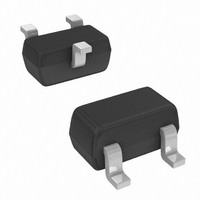
... Marking Information: See Table Below & Page 2 • Ordering Information: See Page 2 • Weight: 0.002 grams (approximate) P/N R1 (NOM) Marking DDTC114GE 10KΩ DDTC124GE 22KΩ DDTC144GE 47KΩ DDTC115GE 100KΩ Maximum Ratings @T = 25°C unless otherwise specified A Characteristic Collector Base Voltage Collector-Emitter Voltage Emitter-Base Voltage ...

Page 2

... I = 0mA 100 www.diodes.com Test Condition Unit ⎯ 50μA C ⎯ 1mA 720μA, DDTC114GE E = 330 μA, DDTC124GE I E ⎯ 160 μA, DDTC144GE μA, DDTC115GE I E μ 50V CB μ 10mA 0.5mA C B ⎯ ⎯ 5mA ⎯ % ⎯ MHz V = 10V -5mA 100MHz ...

Page 3

... Diodes Incorporated and its subsidiaries reserve the right to without further notice to any product herein. Diodes Incorporated does not assume any liability arising out of the application or use of any product described herein; neither does it convey any license under its patent rights, nor the rights of others. The user of products in such applications shall assume all risks of such use and will agree to hold Diodes Incorporated and all the companies whose products are represented on our website, harmless against all damages ...

Related keywords