AXH010A0F93-SRZ Lineage Power, AXH010A0F93-SRZ Datasheet - Page 10
AXH010A0F93-SRZ
Manufacturer Part Number
AXH010A0F93-SRZ
Description
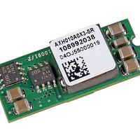
DC/DC Converters & Regulators 4.5-5.5Vin 3.3Vout 10A SMT Remote Sense
Manufacturer
Lineage Power
Type
Step Downr
Series
AXH010r
Specifications of AXH010A0F93-SRZ
Output Current
10A
Input Voltage
4.5 to 5.5V
Output Voltage
3.3V
Screening Level
Industrial
Product Length (mm)
33mm
Product Depth (mm)
13.46mm
Mounting Style
Surface Mount
Pin Count
6
Number Of Outputs
1
Package / Case
SMT
Product
Non-Isolated / POL
Output Power
33 W
Input Voltage Range
4.5 V to 5.5 V
Output Voltage (channel 1)
3.3 V
Output Current (channel 1)
10 A
Package / Case Size
SMD
Output Type
Isolated
Lead Free Status / RoHS Status
Compliant


Lineage Power
Data Sheet
October 1, 2009
Feature Descriptions
Remote On/Off
The Austin Lynx™ SIP power modules feature an
On/Off pin for remote On/Off operation. If not using the
remote On/Off pin, leave the pin open (module will be On).
The On/Off pin signal (Von/off) is referenced to ground. To
switch the module on and off using remote On/Off, connect
an open collector pnp transistor between the On/Off pin and
the VI pin (see Figure 20).
During a logic-low when the transistor is in the Off state, the
power module is On and the maximum
Von/off generated by the module is 0.3V. The maximum
leakage current of the switch when Von/off = 0.3V and VI =
5.5V (Vswitch = 5.2V) is 10 µA. During a logic-high when the
transistor is in the active state, the power module is Off. Dur-
ing this state, Von/off = 2.5V to 5.5V and the maximum Ion/
off = 1mA.
Figure 20. Remote On/Off Implementation.
Output Voltage Set-Point Adjustment
(Trim)
Output voltage set-point adjustment allows the output volt-
age set point to be increased or decreased by connecting
either an external resistor or a voltage source between the
TRIM pin and either the VO pin (decrease output voltage) or
GND pin (increase output voltage).
For TRIM-UP using an external resistor, connect Rtrim-up
between the TRIM and GND pins (Figure 21). The value of
Rtrim-up defined as:
|DVout| is the desired output voltage set-point adjustment
Rbuffer (internal to the module) is defined in Table 1 for vari-
ous models.
R
trim up
–
V
V
=
switch
on/off
+
----------------- - R
ΔV
24080
out
I
–
on/off
buffer
ON/OFF
V
I
kΩ
GND
Austin Lynx
3.0 Vdc - 5.5 Vdc Input, 0.9 Vdc - 3.3 Vdc Output, 10 A
Vo
TM
V
Table 1. Austin Lynx™ Trim Values
Note: V
For example, to trim-up the output voltage of 1.5V
module (AXH010A0M) by 8% to 1.62V, Rtrim-up is
calculated as follows:
Figure 21. Circuit Configuration to trim-up output
For trim-down using an external resistor, connect Rtrim-
down between the TRIM and VOUT pins of the module
(Figure 22). The value of Rtrim-down is defined as:
Vout is the typical set point voltage of a module
|DVout| is the desired output voltage adjustment
Rbuffer (internal to the module) is defined in Table 3 for vari-
ous models
For example, to trim-down the output voltage of 2.5 V mod-
ule (AXH010G) by 8% to 2.3V, Rtrim-down is
calculated as follows:
R
R
R
ΔV
R
out
buffer
ΔV
trim up
trim-down
trim up
SIP Non-Isolated dc-dc Power Modules:
out
VO, set
out
=
3.3 V
2.5 V
2.0 V
1.8 V
1.5 V
1.2 V
1.0 V
0.9 V
–
O, set
–
AXH010A0M
2.5V
=
=
=
=
is the typical output voltage for the unit.
100kΩ
0.12V
voltage.
=
=
0.2V
24080
-------------- - 100k
100.66kΩ
0.12
GND
⎛
⎝
V
------------------------ - 1
out
ΔV
TRIM
–
V
78.7 kW
30.1 kW
–
out
5.11 kW
Rbuffer
100 kW
100 kW
100 kW
O
59 kW
59 kW
0.8
–
⎞ x30100
⎠
R
trim-up
–
R
R
buffer
LOAD
10
kΩ
Related parts for AXH010A0F93-SRZ
Image
Part Number
Description
Manufacturer
Datasheet
Request
R

Part Number:
Description:
Manufacturer:
Lineage Power
Datasheet:

Part Number:
Description:
DC/DC Converters & Regulators 3.3Vout 10A SMT 4.5-5.5Vin
Manufacturer:
Lineage Power
Part Number:
Description:
Manufacturer:
Lineage Power
Datasheet: