MJF18008G ON Semiconductor, MJF18008G Datasheet - Page 8
MJF18008G
Manufacturer Part Number
MJF18008G
Description
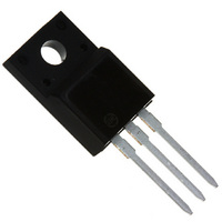
TRANS PWR NPN 8A 450V TO220FP
Manufacturer
ON Semiconductor
Series
SWITCHMODE™r
Datasheet
1.MJE18008G.pdf
(10 pages)
Specifications of MJF18008G
Transistor Type
NPN
Current - Collector (ic) (max)
8A
Voltage - Collector Emitter Breakdown (max)
450V
Vce Saturation (max) @ Ib, Ic
700mV @ 900mA, 4.5V
Current - Collector Cutoff (max)
100µA
Dc Current Gain (hfe) (min) @ Ic, Vce
14 @ 1A, 5V
Power - Max
45W
Frequency - Transition
13MHz
Mounting Type
Through Hole
Package / Case
TO-220-3 Full Pack (Straight Leads)
Lead Free Status / RoHS Status
Lead free / RoHS Compliant
Other names
MJF18008GOS


Figure 22a. Screw or Clip Mounting Position
** For more information about mounting power semiconductors see Application Note AN1040.
technique, a screw torque of 6 to 8 in
sion washer helps to maintain a constant pressure on the package over time and during large temperature excursions.
of 20 in
affecting the package. However, in order to positively ensure the package integrity of the fully isolated device, ON Semi-
conductor does not recommend exceeding 10 in
Destructive laboratory tests show that using a hex head 4−40 screw, without washers, and applying a torque in excess
*Measurement made between leads and heatsink with all leads shorted together
Additional tests on slotted 4−40 screws indicate that the screw slot fails between 15 to 20 in
Laboratory tests on a limited number of samples indicate, when using the screw and compression washer mounting
for Isolation Test Number 1
CLIP
.
lbs will cause the plastic to crack around the mounting hole, resulting in a loss of isolation capability.
Figure 23a. Screw−Mounted
FULLY ISOLATED
MOUNTED
PACKAGE
0.110″ MIN
HEATSINK
LEADS
PLAIN WASHER
NUT
4-40 SCREW
HEATSINK
COMPRESSION WASHER
TEST CONDITIONS FOR ISOLATION TESTS*
.
Figure 23. Typical Mounting Techniques
lbs is sufficient to provide maximum power dissipation capability. The compres-
Figure 22b. Clip Mounting Position
MOUNTING INFORMATION**
CLIP
for Isolation Test Number 2
for Isolated Package
http://onsemi.com
.
lbs of mounting torque under any mounting conditions.
FULLY ISOLATED
MOUNTED
PACKAGE
8
HEATSINK
LEADS
0.099″ MIN
Figure 23b. Clip−Mounted
Figure 22c. Screw Mounting Position
for Isolation Test Number 3
FULLY ISOLATED
MOUNTED
PACKAGE
.
lbs without adversely
HEATSINK
CLIP
HEATSINK
LEADS
0.099″ MIN
Related parts for MJF18008G
Image
Part Number
Description
Manufacturer
Datasheet
Request
R

Part Number:
Description:
ON Semiconductor [VOLTAGE REGULATOR]
Manufacturer:
ON Semiconductor
Datasheet:
Part Number:
Description:
357-036-542-201 CARDEDGE 36POS DL .156 BLK LOPRO
Manufacturer:
ON Semiconductor
Datasheet:
Part Number:
Description:
357-036-542-201 CARDEDGE 36POS DL .156 BLK LOPRO
Manufacturer:
ON Semiconductor
Datasheet:
Part Number:
Description:
357-036-542-201 CARDEDGE 36POS DL .156 BLK LOPRO
Manufacturer:
ON Semiconductor
Datasheet:
Part Number:
Description:
357-036-542-201 CARDEDGE 36POS DL .156 BLK LOPRO
Manufacturer:
ON Semiconductor
Datasheet:
Part Number:
Description:
357-036-542-201 CARDEDGE 36POS DL .156 BLK LOPRO
Manufacturer:
ON Semiconductor
Datasheet:
Part Number:
Description:
357-036-542-201 CARDEDGE 36POS DL .156 BLK LOPRO
Manufacturer:
ON Semiconductor
Datasheet:
Part Number:
Description:
357-036-542-201 CARDEDGE 36POS DL .156 BLK LOPRO
Manufacturer:
ON Semiconductor
Datasheet:
Part Number:
Description:
357-036-542-201 CARDEDGE 36POS DL .156 BLK LOPRO
Manufacturer:
ON Semiconductor
Datasheet:
Part Number:
Description:
357-036-542-201 CARDEDGE 36POS DL .156 BLK LOPRO
Manufacturer:
ON Semiconductor
Datasheet:
Part Number:
Description:
357-036-542-201 CARDEDGE 36POS DL .156 BLK LOPRO
Manufacturer:
ON Semiconductor
Datasheet:
Part Number:
Description:
Manufacturer:
ON Semiconductor
Datasheet:
Part Number:
Description:
Manufacturer:
ON Semiconductor
Datasheet:
Part Number:
Description:
Manufacturer:
ON Semiconductor
Datasheet: