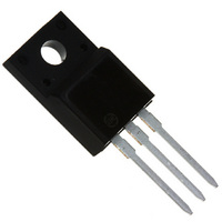
MJF18004G ON Semiconductor, MJF18004G Datasheet - Page 9

MJF18004G
Manufacturer Part Number
MJF18004G
Description
TRANS PWR NPN 5A 450V TO220FP
Manufacturer
ON Semiconductor
Series
SWITCHMODE™r
Datasheet
1.MJE18004G.pdf
(11 pages)
Specifications of MJF18004G
Transistor Type
NPN
Current - Collector (ic) (max)
5A
Voltage - Collector Emitter Breakdown (max)
450V
Vce Saturation (max) @ Ib, Ic
750mV @ 500mA, 2.5A
Current - Collector Cutoff (max)
100µA
Dc Current Gain (hfe) (min) @ Ic, Vce
14 @ 300mA, 5V
Power - Max
35W
Frequency - Transition
13MHz
Mounting Type
Through Hole
Package / Case
TO-220-3 Full Pack (Straight Leads)
Lead Free Status / RoHS Status
Lead free / RoHS Compliant
Other names
MJF18004GOS
Available stocks
Company
Part Number
Manufacturer
Quantity
Price
Company:
Part Number:
MJF18004G
Manufacturer:
PANASONIC
Quantity:
2 000
Part Number:
MJF18004G
Manufacturer:
ON/安森美
Quantity:
20 000
** For more information about mounting power semiconductors see Application Note AN1040.
screw torque of 6 to 8 in
a constant pressure on the package over time and during large temperature excursions.
cause the plastic to crack around the mounting hole, resulting in a loss of isolation capability.
package. However, in order to positively ensure the package integrity of the fully isolated device, ON Semiconductor does not recom-
mend exceeding 10 in
Figure 22a. Screw or Clip Mounting
Position for Isolation Test Number 1
Laboratory tests on a limited number of samples indicate, when using the screw and compression washer mounting technique, a
Destructive laboratory tests show that using a hex head 4−40 screw, without washers, and applying a torque in excess of 20 in
*Measurement made between leads and heatsink with all leads shorted together
Additional tests on slotted 4−40 screws indicate that the screw slot fails between 15 to 20 in
CLIP
Figure 23a. Screw−Mounted
FULLY ISOLATED
MOUNTED
PACKAGE
.
.
lbs of mounting torque under any mounting conditions.
lbs is sufficient to provide maximum power dissipation capability. The compression washer helps to maintain
0.110″ MIN
HEATSINK
LEADS
PLAIN WASHER
NUT
4-40 SCREW
HEATSINK
COMPRESSION WASHER
TEST CONDITIONS FOR ISOLATION TESTS*
Figure 23. Typical Mounting Techniques
Figure 22b. Clip Mounting Position
MOUNTING INFORMATION**
CLIP
for Isolation Test Number 2
for Isolated Package
http://onsemi.com
FULLY ISOLATED
MOUNTED
PACKAGE
9
HEATSINK
LEADS
0.099″ MIN
Figure 23b. Clip−Mounted
Figure 22c. Screw Mounting Position
for Isolation Test Number 3
.
lbs without adversely affecting the
FULLY ISOLATED
MOUNTED
PACKAGE
HEATSINK
CLIP
HEATSINK
LEADS
.
lbs will
0.099″ MIN


