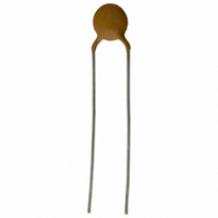
PTCCL07H141HTE Vishay, PTCCL07H141HTE Datasheet - Page 18

PTCCL07H141HTE
Manufacturer Part Number
PTCCL07H141HTE
Description
PTC CP LDD 7D00 A140 265 140 T E3
Manufacturer
Vishay
Series
661r
Datasheet
1.PTCCL05H470FTE.pdf
(22 pages)
Specifications of PTCCL07H141HTE
Voltage - Max
265V
Current - Hold (ih) (max)
140mA
Current - Trip (it)
210mA
Current - Max
800mA
Package / Case
Radial
Lead Free Status / RoHS Status
Contains lead / RoHS non-compliant
R Min/max
-
Time To Trip
-
Lead Free Status / RoHS Status
Contains lead / RoHS non-compliant
Other names
2322 661 51413
232266151413
BC1369
PTCCL07H141HBC
232266151413
BC1369
PTCCL07H141HBC
BCcomponents
Table 6
Characteristics concerning taped thermistors
2000 Oct 13
D
T
d
P
P
P
F
W
W
W
W
H
H
H
H
D
t
L
Minimum pull out force of the component
Minimum pull off force of adhesive tape
Minimum tearing force tape
Maximum pull off force tape-reel
Storage conditions
Storage temperature range
Maximum relative humidity
SYMBOL
0
1
h
h
PTC thermistors for
overload protection
1
2
3
0
0
0
1
2
Tape and other device dimensions; see Figs 1 and 25
body diameter
total maximum thickness
lead diameter
pitch between thermistors:
feed hole pitch
feed hole centre to lead centre
component alignment
lead to lead distance
component alignment
tape width
hold down tape width
hole position
hold down tape position
component height
component body to seating plane
component top to seating plane
lead-wire clinch height
feed hole diameter
total tape thickness
length of snipped lead
12 mm
12 mm
PARAMETER
PARAMETER
DIMENSIONS
see Table 1
(mm)
12.7
25.4
12.7
3.81
0.6
12.3
18
16
3.0
0.9
5
9
4
11
0
0
4
18
see Table 2
see Table 1
see Table 1
5 N
6 N
15 N
5 N
80%
25 to +40 C
TOLERANCE
+0.6 to 0.1
+1 to 0.5
10%
0.5
0.3
0.7
1.3
0.5
0.5
0.2
1
2
2
1
30 to 60 V, 145 V and
265 V (T
cumulative pitch error
guaranteed between
component and tape
guaranteed between
component and tape
with cardboard tape 0.5 0.1 mm
1 mm/20 pitches
VALUE
REMARKS
Product specification
s
= 140 C)


