F110J476MD3 Nichicon, F110J476MD3 Datasheet
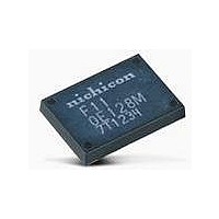
F110J476MD3
Manufacturer Part Number
F110J476MD3
Description
Aluminum Organic Polymer Capacitors 6.3volts 47uF D Case
Manufacturer
Nichicon
Series
F11r
Datasheet
1.F110E128MF3.pdf
(2 pages)
Specifications of F110J476MD3
Esr
20 mOhms
Operating Temperature Range
- 55 C to + 105 C
Termination Style
SMD/SMT
Dimensions
5.3 mm W x 8.5 mm L x 2 mm H
Dissipation Factor Df
5
Leakage Current
30 uAmps
Load Life
5000 Hrs
Product
Organic Polymer Aluminum - Chip Capacitors
Capacitance
47 uF
Tolerance
20 %
Voltage Rating
6.3 Volts
Ripple Current
3.5 Amps
Lead Free Status / RoHS Status
Lead free / RoHS Compliant


DECOUPLING DEVICE FOR HIGH FREQUENCY
F11
Case Code
Higher Capacitance.
Low ESR, Low ESL,High ripple current.
Resin-molded Chip.
Designed for surface mounting on high density PC board.
Load life of 5000 hours at + 105°C.
Compliant to the RoHS directive (2002/95/EC).
Type numbering system (Example : 2.5V 220µF)
F 1 1
Dimensions
Marking
1
D
F
2
S
Rated Voltage
(Voltage code)
1
S
3
W
F11
0E128M
8J1234
2
2
16.7
8.5
0
L
L
4
P
1
2
L
E
1
5
0.2
0.2
S
2 2 7 M D L
6
3
15.6
7.3
7
Lot No.
L
8
2
0.2
0.2
Capacitance Tolerance
Seriese
W
9
1
Rated Capacitance
(Capacitance code)
12.1
5.3
10
W
F case only
1
11
0.2
0.2
12 13 14
A H
1.7
3.6
code
W
L
K
2
0.2
0.2
Capacitance tolerance
Tape width
2.0MAX.
2.5MAX.
(mm)
Rated capacitance
16
24
H
Rated voltage
Taping code
Case code
Reel Dia
H
Low ESR
0.9
1.5
mm)
180
330
Series
S
1
0.2
0.1
0.6
1.3
S
2
0.2
0.1
Category Temperature Range
Capacitance Tolerance
Dissipation Factor
ESR
Leakage Current
Damp Heat
(Steady State)
Temperature Cycles
Temperature Change
Characteristics
Resistance
to Soldering Heat
Surge
Endurance
Marking
Item
Specifications
Standard ratings
Cap.(
0.5
1.5
1200
S
3
µ
100
220
330
600
800
0.2
0.2
F
47
)
3.3
7.0
P
0.2
0.2
(mm)
Code
476
107
227
337
607
807
128
( ) The series in parentheses are being developed.
Please contact to your local Nichicon sales office when
these series are being designed in your application.
Capacitance Change
Dissipation Factor
ESR
Leakage Current
Refer to next table
Refer to next table
After 5 minute’s application of rated voltage,
leakage current is not more than 0.1CV
At 60 C 90%RH 500hours (No voltage applied)
Capacitor meets the following characteristics after solder reflow
(Peak: 240 C for 10sec, 2cycle).
Temperature should be measured at the terminals.
After application of 115% of rating voltage at the rate of
30 seconds ON, 30 seconds OFF, for 1000 successive
test cycles at 105 C, capacitors meet the characteristics
requirements listed below.
After 5000 hours’ application of rated voltage at 105 C, they will meet
the specified value for life charecteristics listed below.
Printed on the package top.
55 to +105 C
20% (at 120Hz)
55 C / +105 C 30minutes each 5cycle
Capacitance Change .. Within 20 to +30% of the initial specified value
Dissipation Factor ....... 200% or less than the Initial specified value
ESR ............................ 200% or less than the Initial specified value
Leakage Current ......... Initial specified value or less
Capacitance Change .. Within 20% of the Initial specified value
Dissipation Factor ....... 200% or less than the Initial specified value
ESR ............................ 200% or less than the Initial specified value
Leakage Current ......... Initial specified value or less
Capacitance Change .. Within 20% of the Initial specified value
Dissipation Factor ....... Initial specified value or less
ESR ............................ Initial specified value or less
Leakage Current ......... Initial specified value or less
Capacitance Change .... Within 20% of the initial specified value
Dissipation Factor ......... 200% or less than the Initial specified value
ESR .............................. 200% or less than the Initial specified value
Leakage Current ........... Initial specified value or less
Capacitance Change .... Within 20% of the initial value
Dissipation Factor ......... 200% or less than the Initial specified value
ESR .............................. 200% or less than the Initial specified value
Leakage Current ........... Initial specified value or less
V
2.5
( D )
0E
D
D
F
F
Performance Characteristics
Within 20 to +0%
Initial specified value or less
Initial specified value or less
Initial specified value or less
55 C
0G
( D )
D
D
4
F
( D )
6.3
0J
D
F
+105 C
Within 0 to +50%
150% or less than the Initial specified value
150% or less than the Initial specified value
10 times Initial specified value
CAT.8100Y
Related parts for F110J476MD3
Image
Part Number
Description
Manufacturer
Datasheet
Request
R

F110J476MD3 Summary of contents
Page 1
... The series in parentheses are being developed. Please contact to your local Nichicon sales office when these series are being designed in your application. Performance Characteristics Capacitance Change .. Within 20 to +30% of the initial specified value Dissipation Factor ....... 200% or less than the Initial specified value ESR ...
Page 2
DECOUPLING DEVICE FOR HIGH FREQUENCY F11 Ratings Table < > Standard Rated Rated Volt Case Capacitance Part Number (V) code (µF) F110E107MDL 0100 D D F110E227MDL 0220 D D 2.5 F110E607MFK 0600 F F F110E128MFK 1200 F F F110G476MDL 0047 ...