60R050-PB Littelfuse Inc, 60R050-PB Datasheet
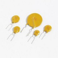
PTC Resettable Fuses 60V .5A-HD 40A MAX

60R050-PB

Manufacturer Part Number
60R050-PB
Description
PTC Resettable Fuses 60V .5A-HD 40A MAX
Manufacturer
Littelfuse Inc
Datasheet

Specifications of 60R050-PB

Hold Current
0.5 Amp
Trip Current
1 Amp
Current Rating (max)
40 Amps
Resistance
1.17 Ohms
Maximum Voltage
60 VoltsDC
Termination Style
Radial
Mounting Style
Through Hole
Current Rating
40 Amps
Dimensions
7.9 mm D
Lead Spacing
0.51 mm
Operating Temperature Range
- 40 C to + 85 C
Lead Free Status / RoHS Status
Lead free / RoHS Compliant
Specifications are subject to change without notice.
Please refer to www.littelfuse.com/series/60R.html for current information.
I
I
V
I
P
©2008 Littelfuse, Inc.
hold
trip
max
d
max
Agency Approvals
AGENCY
Electrical Characteristics
= Power dissipated from device when in the tripped state at 20°C still air.
= Trip current: minimum current at which the device will trip in 20°C still air.
= Hold current: maximum current device will pass without tripping in 20°C still air.
= Maximum fault current device can withstand without damage at rated voltage (V
= Maximum voltage device can withstand without damage at rated current (I max)
Part Number
60R020
60R025
60R030
60R040
60R050
60R065
60R075
60R090
60R250
60R300
60R375
60R010
60R135
60R160
60R185
60R110
60R Series
AGENCY FILE NUMBER
E183209
R50119318
3.00
0.10
0.20
0.25
0.30
0.40
0.50
0.65
0.75
0.90
1.35
1.60
1.85
2.50
3.75
I
1.10
(A)
hold
0.20
0.40
0.50
0.60
0.80
2.20
2.70
3.20
3.70
5.00
6.00
1.00
1.30
1.50
1.80
7 .50
I
(A)
trip
Radial Leaded > 60R Series
POLYFUSE
(Vdc)
V
60
60
60
60
60
60
60
60
60
60
60
60
60
60
60
60
max
Revised: October 24, 2008
I
(A)
40
40
40
40
40
40
40
40
40
40
40
40
40
40
40
40
max
max
)
®
Resettable PTCs
max.
R
R
R
Caution: Operation beyond the specified rating may result in damage and possible arcing
and flame.
0.38
0.41
0.45
0.49
0.56
0.77
0.88
0.92
0.99
2.10
2.50
2.80
3.20
(W)
1.50
1.70
1.90
P
min
typ
1max
Description
The 60R Series radial leaded device is designed to provide
overcurrent protection for (≤60V) applications where space
is not a concern and resettable protection
is preferred.
Features
Applications
d
= Typical resistance of device in initial (un-soldered) state.
lead–free
and peripherals
= Minimum resistance of device in initial (un-soldered) state.
= Maximum resistance of device at 20°C measured one hour after tripping or reflow
soldering of 260°C for 20 sec.
Current
Maximum Time
12.50
15.00
18.75
2.00
8.00
0.50
1.00
1.25
1.50
2.50
3.25
3.75
4.50
5.50
6.75
9.25
(A)
To Trip
(Sec.)
12.60
15.60
19.80
24.00
Time
11.40
4.00
2.20
2.50
3.00
3.80
4.00
5.30
6.30
8.20
9.60
7 .20
2.500
0.880
0.550
0.500
0.310
0.250
0.200
0.150
0.120
0.090
0.080
0.050
0.040
0.030
1.830
1.250
R
(Ω)
Resistance
min
epoxy polymer insulating
material meets UL 94V-0
requirements
4.400
3.000
0.720
0.600
0.470
0.380
0.300
0.220
0.080
R
2.100
1.290
0.190
0.130
0.100
7 .500
1.170
(Ω)
1max
Approvals
X
X
X
X
X
X
X
X
X
X
X
X
X
X
X
X
Agency
60R Series
X
X
X
X
X
X
X
X
X
X
X
X
X
X
X
X

Related parts for 60R050-PB

60R050-PB Summary of contents

Page 1

... Part Number hold trip (A) (A) 60R010 0.10 0.20 60R020 0.20 0.40 60R025 0.25 0.50 60R030 0.30 0.60 60R040 0.40 0.80 60R050 0.50 1.00 60R065 0.65 1.30 60R075 0.75 1.50 60R090 0.90 1.80 60R110 1.10 2.20 60R135 1.35 2.70 60R160 1.60 3.20 60R185 1 ...

Page 2

... Temperature Rerating -40°C -20°C Part Number 60R010 0.16 0.14 60R020 0.31 0.27 60R025 0.39 0.34 60R030 0.47 0.41 60R040 0.62 0.54 60R050 0.78 0.68 60R065 1.01 0.88 60R075 1.16 1.02 60R090 1.40 1.22 60R110 1.71 1.50 60R135 2.09 1.84 60R160 2.48 2 ...

Page 3

Soldering Parameters - Wave Soldering Refer to the condition recommended by the flux manufacturer. Pre-Heating Zone Max. ramping rate should not exceed 4°C/ Sec. Max. solder Soldering Zone temperature should not exceed 260°C Cooling by natural Cooling Zone convection in ...

Page 4

... Part Number Inches mm Inches Max. Max. Max. 60R010 0. 0.50 60R020 0. 0.46 60R025 0. 0.50 60R030 0. 0.50 60R040 0. 0.53 60R050 0. 0.54 60R065 0.37 9.4 0.57 60R075 0.40 10.2 0.59 60R090 0.44 11.2 0.62 60R110 0.51 13 0.72 60R135 0.53 13.58 0.78 60R160 0.60 15.36 ...

Page 5

... 60R010XPR 60R020XU 60R020 0.20 60R020XPR 60R025XU 60R025 0.25 60R025XPR 60R030XU 60R030 0.30 60R030XPR 60R040XU 60R040 0.40 60R040XPR 60R050XU 60R050 0.50 60R050XPR 60R065XU 60R065 0.65 60R065XPR 60R075XU 60R075 0.75 60R075XPR 60R090XU 60R090 0.90 60R090XPR 60R110XU 60R110 1.10 60R110XMR 60R135XF 60R135 1.35 60R135XMR ...

Page 6

POLYFUSE Tape and Ammo Specifications Devices taped using EIA468-B/IE286-2 standards. See table below and Figure 1 for details. Dimension Carrier tape width Hold down tape width Top distance between tape edges Sprocket hole position Sprocket hole diameter* Abscissa to plane(straight ...

Page 7

Tape and Ammo Diagram Δh Δ ©2008 Littelfuse, Inc. ©2008 Littelfuse, Inc. Specifications are subject to change without notice. Please refer to www.littelfuse.com/series/60R.html for current information. POLYFUSE Resettable PTCs ...

Related keywords