24140 Cinch Connectors, 24140 Datasheet - Page 274
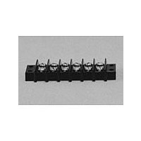
24140
Manufacturer Part Number
24140
Description
Manufacturer
Cinch Connectors
Type
Barrier Stripr
Datasheet
1.24140.pdf
(282 pages)
Specifications of 24140
Number Of Contacts
24POS
Number Of Contact Rows
2
Termination Method
Screw
Mounting Style
Panel
Contact Pitch (mm)
9.53mm
Current Rating (max)
15A
Operating Temp Range
-48C to 148C
Housing Material
Phenolic
Body Orientation
Straight
Operating Voltage (max)
250VAC
Product Height (mm)
28.58mm
Product Length (mm)
245.28mm
Wire Gauge
16
Lead Free Status / RoHS Status
Compliant
Available stocks
Company
Part Number
Manufacturer
Quantity
Price
Company:

Part Number:
241402B91200G
Manufacturer:
ATH
Quantity:
1 020
Company:
Part Number:
241402B92200G
Manufacturer:
ATH
Quantity:
414
Company:
Part Number:
241404B91200G
Manufacturer:
ATH
Quantity:
300
Company:
Part Number:
241404B92200G
Manufacturer:
ATH
Quantity:
262
Company:
Part Number:
241409B91200G
Manufacturer:
ATH
Quantity:
100


.085 in. (2.16mm)
Density
Miniature Ribbon
Insulator: Gray UL94V-0 rated glass-filled polyester
Contact: Copper alloy
Contact Plating: 30µin. select gold over 50µin. select nickel
Mounting Hardware Plating: Tin-lead
Operating Temperature: -50°C to +105°C
Shock: 50G Peak, per EIA Std. RS364, TP27, Condition A
Vibration: 3 cycles @ 10-55Hz in each of 3 axes per EIA Std.
Moisture Resistance: Per EIA Std. RS364, TP31, Condition B,
Durability: 200 mating/unmating cycles
Mating / Unmating Forces:
Call Toll Free: 1 (800) 323-9612
Insertion Loss:
@ 25°C, 1kHz, 1 VAC RMS max.
Insulation Resistance:
Contact Resistance:
Dissipation Factor:
Low-pass (single-pole, capacitive) filtered contacts reduce inbound and outbound conducted
EMI standard capacitance values of 50pF through 1,200pF.
Saves space by incorporating required filter functions directly into footprint of I/O connector.
Available as straight Solder Tail plug for solder termination to printed circuit board
(nominal thickness through .093") and as plug/socket adapter, in 50-position size.
All-plastic design reduces cost.
All plugs lock with InstaLatch passive latch feature for automatic latching.
Adapters available with InstaLatches, with Bail Latches, or with no latches on socket side.
Available with through holes, #4-40 holes, #6-32 holes, or M3 holes for mounting/latching.
RF Current Rating:
Leakage Current:
Capacitance
Contact Rating:
Voltage Rating:
Voltage Surge:
Size
50
364, TP28, Condition A
1,000pF+15%
1,200pF+15%
100pF+15%
220pF+15%
470pF+15%
820pF+15%
50pF+15%
standard; tin-lead on solder tails
Mating Force (max.)
with InstaLatches
Lb.
32
with Step 7B excluded
500VDC @ sea level
3 Amps
0.3 Amps
10mA maximum per contact when subjected to
1000 VAC test voltage, applied over 30 seconds
and held for 60 seconds per FCC Part 68.5
Withstands 1,500V peak longitudinal voltage
surge with 10µsec. risetime, 160µsec. decay
6 milliohms maximum, per EIA Std. RS364, TP6
5000 Megohms minimum
5% maximum @ 25°C, 1kHz and
1 VAC RMS maximum
14.52
Kg
10MHz
3
3
3
-
-
-
-
Filtered
Vertical-Mount Solder Tail
and Male/Female Adapter
Unmating Force (min.)
without InstaLatches
Lb.
7
Insertion Loss, min. (dB, @ 25°C, @ 50 ohm, no load, per MIL-STD-220)
30MHz
5
3
3
3
-
-
-
Kg
3.18
50MHz
6-48
11
16
16
16
4
-
-
70MHz
14
20
20
20
7
-
-
100MHz
12
20
20
20
20
2
3
500MHz
14
14
14
14
14
14
14
1GHz
11
11
11
11
11
11
11
Related parts for 24140
Image
Part Number
Description
Manufacturer
Datasheet
Request
R

Part Number:
Description:
Standard Card Edge Connectors CINCH BLK CARD GUIDE
Manufacturer:
Cinch Connectors

Part Number:
Description:
TERMINAL BLOCK JUMPER TYPE F
Manufacturer:
Cinch Connectors
Datasheet:
Part Number:
Description:
D-Subminiature Connectors MCHNED PIN 20-24AWG
Manufacturer:
Cinch Connectors
Datasheet:
Part Number:
Description:
Terminal Block,4 Contacts,0.44 Pitch
Manufacturer:
Cinch Connectors
Datasheet:

Part Number:
Description:
Terminal Block,8 Contacts,0.375 Pitch
Manufacturer:
Cinch Connectors
Datasheet: