5-1437652-4 TE Connectivity, 5-1437652-4 Datasheet - Page 41
5-1437652-4
Manufacturer Part Number
5-1437652-4
Description
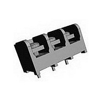
Barrier Strip; Tri-Barrier; Raised; 0.375 in. CL; Single Level; 1 Row; 3 Cir.; Vertica
Manufacturer
TE Connectivity
Type
Barrier Stripr
Specifications of 5-1437652-4
Number Of Contacts
3POS
Number Of Contact Rows
1
Termination Method
Solder
Contact Plating
Bright Tin
Mounting Style
Through Hole
Contact Pitch (mm)
9.53mm
Current Rating (max)
25/ContactA
Contact Material
Copper Alloy/Steel
Housing Material
Thermoplastic
Gender
PL
Body Orientation
Straight
Product Height (mm)
15.88mm
Product Depth (mm)
17.78mm
Product Length (mm)
30.12mm
Wire Gauge
12-22
Agency Approvals
UL Recognized, CSA
Base Style
Raised
Color
Black
Current, Rating
25 A
Material, Screw
Steel
Mount Angle
Vertical
Number Of Poles
3
Number Of Rows
Tri-Barrier
Pin Spacing
0.375(9.53) In.(mm)
Plating, Screw
Bright Zinc⁄Chrome
Primary Type
Barrier
Screw Head Type
Phil-Slot
Special Features
High Voltage, Tri-Barrier
Terminal Style
Printed Circuit Pin 5.08 [0.200]
Top Hardware
Steel Clamp-Plate Combo Head Screws
Voltage, Rating
300 V
Wire, Awg
22-12
Lead Free Status / RoHS Status
Compliant
Available stocks
Company
Part Number
Manufacturer
Quantity
Price
Company:

Part Number:
5-1437652-4
Manufacturer:
CITIZEN
Quantity:
1 650


152
Catalog 1308389
Revised6-07
www.tycoelectronics.com
Ordering Information
A
B
C
D
Single Screw Dual-Barrier Strip
SSB
Contact Spacing
(Center-to-Center)
7 =.4375 (7/16)
Base Options
C=Closed Base
F=Flat Base
R=Raised Base
T=Turret Base
Mounting Options
(See illustration below)
E=Open end positions, with
F=Open end positions, without
G=Open end positions, with
M=Open end positions, without
P=All positions filled with contacts,
(Available only with 01, 04, 05,
07, 09, 12, 13, 15 style bottom
terminals)
mounting inserts, without end
barriers
mounting inserts, with end
barriers
with end barriers
mounting inserts, without end
barriers
mounting inserts, with end
barriers
Dimensions are in millimeters
and inches unless otherwise
specified.
SSB 7 F P 06 02 02 11
BUCHANAN Terminal Blocks
0.4375” [11.1] Pitch, Series SSB7
A
F
G
E
B
No. of Circuits (Not Positions)
Must conform to mounting options
02 to 32 circuits (P & H mounting)
02 to 27 circuits (M, E, F & G
Terminal Style
01=Solder Tail
02=Printed Circuit Pin
03=Non-Feed Through (with C
04=Extended Printed Circuit Pin
05=Quick Connects
06=90° bend, .46" x .11" (with F
07=Wire Wrap
08=90° bend, .75" x .11" (with F
12=90° bend, .21" x .65"
13=90° bend, .36" x .50"
14=90° bend, .41" x .16" (with F
15=90° bend, .51" x .35"
16=90° bend, .32" x .25" (with F
Top Hardware Options
00=No top hardware (Separately
01=Bright zinc and chromate
02=Bright zinc and chromate
03=Stainless steel binding head
04=Nickel plated brass binding
09=Nickel plated brass screw and
Dimensions are shown for
reference purposes only.
Specifications subject
to change.
base only)
base only)
base only)
base only)
base only)
packaged binding head screws
supplied at no cost)
plated steel binding head
screw
plated steel screw and captive
clamp - Do not order with other
top hardware
screw
head screw
captive clamp - Do not order
with other top hardware
C
mounting)
D
E
USA: 1-800-522-6752
Canada: 1-905-470-4425
Mexico: 01-800-733-8926
C. America: 52-55-1106-0803
Note:
are RoHS Compliant.
(Continued)
F
All part numbers
G
H
80=Single-sided solder tab
81=Double-sided solder tab
Quick-Connect Blades
(supplied with 01 screw)
.250 wide
Circuit Identification Options
11 = 12345...
12 = ...54321
13 =
14 =
15 =
16 =
x.032
thick
20
21
22
23
24
25
26
27
28
29
30
31
32
33
34
35
36
H
12345...
...54321
South America: 55-11-2103-6000
Hong Kong: 852-2735-1628
Japan: 81-44-844-8013
UK: 8706-080-208
.187 wide
x.020
thick
40=
41=
42=
43=
44=
45=
46=
47=
48=
49=
50=
51=
52=
53=
54=
55=
56=
LR25557
E63810
Related parts for 5-1437652-4
Image
Part Number
Description
Manufacturer
Datasheet
Request
R

Part Number:
Description:
Conn Shrouded Header HDR 14 POS 2.54mm Solder ST Thru-Hole
Manufacturer:
TE Connectivity
Datasheet:

Part Number:
Description:
Conn D-Subminiature PIN 9 POS 2.77mm Solder ST Thru-Hole 9 Terminal 1 Port
Manufacturer:
Tyco Electronics
Datasheet:
Part Number:
Description:
Conn D-Subminiature PIN 9 POS 2.77mm Solder ST Thru-Hole 9 Terminal 1 Port
Manufacturer:
Tyco Electronics

Part Number:
Description:
Conn Shrouded Header HDR 14 POS 2.54mm Solder RA Thru-Hole Tube
Manufacturer:
TE Connectivity
Datasheet:

Part Number:
Description:
Conn Shrouded Header HDR 14 POS 2.54mm Solder RA Thru-Hole
Manufacturer:
TE Connectivity
Datasheet:

Part Number:
Description:
Manufacturer:
TE Connectivity
Datasheet:

Part Number:
Description:
Manufacturer:
TE Connectivity
Datasheet:

Part Number:
Description:
Conn Shrouded Header HDR 4 POS 2.54mm Solder ST Thru-Hole
Manufacturer:
TE Connectivity
Datasheet:

Part Number:
Description:
Conn Shrouded Header HDR 3 POS 2.54mm Solder RA Thru-Hole
Manufacturer:
TE Connectivity
Datasheet:

Part Number:
Description:
Conn Shrouded Header HDR 3 POS 2.54mm Solder ST Thru-Hole
Manufacturer:
TE Connectivity
Datasheet:

Part Number:
Description:
Conn Shrouded Header HDR 2 POS 2.54mm Solder ST Thru-Hole Tube
Manufacturer:
TE Connectivity
Datasheet:

Part Number:
Description:
Conn IDC Connector PIN 2 POS 2.54mm IDT ST Cable Mount Strip
Manufacturer:
TE Connectivity
Datasheet:

Part Number:
Description:
Conn IDC Connector RCP 2 POS 2.54mm IDT ST Cable Mount Strip
Manufacturer:
TE Connectivity
Datasheet:

Part Number:
Description:
Conn Shrouded Header HDR 2 POS 2.54mm Solder ST Thru-Hole Tube
Manufacturer:
TE Connectivity
Datasheet:

Part Number:
Description:
Conn Shrouded Header HDR 2 POS 2.54mm Solder ST Thru-Hole Tube
Manufacturer:
TE Connectivity
Datasheet: