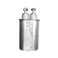
SCRN213R Cornell Dubilier Electronics (CDE), SCRN213R Datasheet - Page 3

SCRN213R
Manufacturer Part Number
SCRN213R
Description
Manufacturer
Cornell Dubilier Electronics (CDE)
Datasheet
1.SCRN213R.pdf
(3 pages)
Specifications of SCRN213R
Capacitance
5uF
Tolerance (+ Or -)
10%
Voltage
400VDC
Operating Temp Range
-40C to 65C
Mounting Style
Screw Terminal
Failure Rate
Not Required
Product Length (mm)
54.864mm
Product Depth (mm)
33.274mm
Product Height (mm)
98.552mm
Product Diameter (mm)
Not Requiredmm
Lead Spacing (nom)
Not Requiredmm
Lead Diameter (nom)
Not Requiredmm
Lead Free Status / RoHS Status
Not Compliant
How to Choose a Commutating Capacitor
1. From circuit analysis or measurement, determine
application values for these six parameters:
2. Choose a capacitor from the ratings table of the desired
nominal capacitance with a peak voltage rating no less than
your maximum peak voltage.
3. Check that your application’s rms current is no more
than the capacitor’s Max. Amps RMS. You can calculate
Using Volt-Ampere Ratings
T
of the sine wave voltage and current that may be applied at
65 ºC without overheating the capacitor and reducing its
expected life. For other temperatures and pulsed current, use
the multipliers of Figures 2 and 3 to derate the Max VA rating.
The Max Amps RMS rating is set by the capability of the
capacitor terminals. Exceeding this limit can damage the
terminals and cause capacitor failure.
Calculate the capacitor’s actual VA load as the product of the
rms voltage across the capacitor and the rms current through
the capacitor. To calculate rms current for an applied sine
wave or squarewave voltage, use these equations.
For a sinewave voltage the current is:
and for a squarewave the current is:
where (f) is repetition frequency in Hz, C is nominal
capacitance in µF, ∆V the peak-to-peak squarewave amplitude
in volts, (t) is the pulse width in µs and T is the pulse period
in µs.
T
he capacitors maximum VA rating is the maximum product
he peak current for the square wave voltage is:
CDE Cornell Dubilier • 1605 E. Rodney French Blvd. • New Bedford, MA 02744 • Phone: (508)996-8561 • Fax: (508)996-3830 • www.cde.com
Nominal capacitance in µF
Current pulse width in µs
Current pulse period in µs
Maximum peak voltage
Continuous AC voltage in Vrms
Maximum volt-amps (VA)
Irms = C∆V/[0.64(tT)
Irms = 2π fCVrmsX10
Ipeak = C∆V/0.64t
0.5
] = Ipeak(t/T)
COPY & PASTE A CDE PART NUMBER TO CHECK STOCK ONLINE:
-6
0.5
Type SCR
the
following
4. Check that your application’s volt-amperes is not more
than the capacitor’s VA capability. The VA capability is the
max VA rating times the Volt-Ampere multiplier from Figure
2 (Current Pulse Width) and that times the Volt-Ampere
Multiplier from Figure 3 (Ambient Temperature). See the
following section for more on using volt-ampere multipliers
.
If you need a greater VA capability, repeat these steps for a
higher peak voltage capacitor or consider connecting units in
parallel to divide the VA required. For up to peak voltage of
600 V, you may also consider polypropylene film dielectric
units, Catalog Numbers SCRN262R through SCRN266R,
with higher VA capability.
current from your Vrms using the equations in the
section.
Polypropylene
Commutating Capacitors
PP Film/Paper
Pulse Wave Applications
ΔV
V peak
I peak
Paper
Voltage
Current
Figure 1
Figure 2
Figure 3
GO


