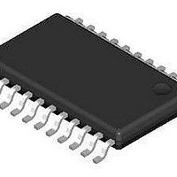
AX5151-TSSOP24-TU AXSEM, AX5151-TSSOP24-TU Datasheet - Page 20

AX5151-TSSOP24-TU
Manufacturer Part Number
AX5151-TSSOP24-TU
Description
RF Transmitter TSSOP-Class-IC
Manufacturer
AXSEM
Type
Single Chip Transceiverr
Datasheet
1.AX5151-TSSOP24-TU.pdf
(43 pages)
Specifications of AX5151-TSSOP24-TU
Package / Case
TSSOP-24
Operating Frequency
400 MHz to 940 MHz
Maximum Operating Temperature
+ 70 C
Mounting Style
SMD/SMT
Operating Supply Voltage
2.3 V to 3.6 V
Supply Current
100 mA
Lead Free Status / RoHS Status
Lead free / RoHS Compliant
20
Circuit Description
5.1.
The AX5151 uses an on-chip voltage regulator to create a stable supply voltage for the
internal circuitry at pin VREG from the primary supply VDD_IO. All VDD pins of the device must
be connected to VREG. The antenna pins ANTP and ANTN must be DC biased to VREG. The
I/O level of the digital pins is VDD_IO.
The voltage regulator requires a 1µF low ESR capacitor at pin VREG.
In power-down mode the voltage regulator typically outputs 1.7 V at VREG, if it is powered-
up its output rises to typically 2.5 V. At device power-up the regulator is in power-down
mode.
The voltage regulator must be powered-up before receive or transmit operations can be
initiated. This is handled automatically when programming the device modes via the
PWRMODE register.
Register VREG contains status bits that can be read to check if the regulated voltage is
above 1.3 V or 2.3 V, sticky versions of the bits are provided that can be used to detect low
power events (brown-out detection).
5.2.
The on-chip crystal oscillator allows the use of an inexpensive quartz crystal as the RF
generation subsystem’s timing reference. Although a wider range of crystal frequencies can
be handled by the crystal oscillator circuit, it is recommended to use 16 MHz as reference
frequency since this choice allows all the typical SRD band RF frequencies to be generated.
The oscillator circuit is enabled by programming the PWRMODE register. At power-up it is not
enabled.
To adjust the circuit’s characteristics to the quartz crystal being used without using additional
external components, both the transconductance and the tuning capacitance of the crystal
oscillator can be programmed.
The transconductance is programmed via register bits XTALOSCGM[3:0] in register XTALOSC.
The integrated programmable tuning capacitor bank makes it possible to connect the
oscillator directly to pins CLK16N and CLK16P without the need for external capacitors. It is
programmed using bits XTALCAP[5:0] in register XTALCAP.
To synchronize the receiver frequency to a carrier signal, the oscillator frequency could be
tuned using the capacitor bank however, the recommended method to implement
frequency synchronization is to make use of the high resolution RF frequency generation sub-
system together with the Automatic Frequency Control, both are described further down.
Alternatively a single ended reference (TXCO, CXO) may be used. The CMOS levels should
be applied to CLK16P via an AC coupling with the crystal oscillator enabled.
Version 1.0
Voltage Regulator
Crystal Oscillator
Datasheet AX5151


