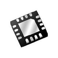
ATR4254-PEPY Atmel, ATR4254-PEPY Datasheet

ATR4254-PEPY
Specifications of ATR4254-PEPY
Related parts for ATR4254-PEPY
ATR4254-PEPY Summary of contents
Page 1
... Low Power Consumption Electrostatic sensitive device. Observe precautions for handling. 1. Description The ATR4254 is an integrated low-noise AM/FM antenna impedance matching circuit in BiCMOS technology. The device is designed specifically for car applications and is suitable for windshield and roof antennas. Figure 1-1. Block Diagram ...
Page 2
... Table 2-1. Pin Description Pin SSO16 Pin QFN16 ATR4254 2 Figure 2- FMOUT AGCADJ 13 VREF1 12 AMOUT1 11 AMOUT Symbol Function FMIN FM input GND1 Ground for FM part FMGAIN FM gain adjustment AGC AGC output VREF2 Reference voltage 2 output NC Not connected GND2 Ground for AM part AMIN AM input ...
Page 3
... The maxi- mum current which flows into the AGC pin is approximately 1 mA. In low-end applications, the AGC function is not necessary and the external components can therefore be omitted. 4879A–AUDR–09/05 Internal Circuit at Pin FMIN 1 FMIN Internal Circuit at Pin FMGAIN FMGAIN ATR4254 ESD ESD 3 3 ...
Page 4
... If AGCADJ is open, the threshold is set to 106 dBµV. Figure 3-4. 3.6 FMOUT The FM amplifier output is an open collector of a bipolar RF transistor. It should be connected to V via a coil. S Figure 3-5. ATR4254 4 Internal Circuit at Pin AGC AGC 4 Internal Circuit at Pin AGCADJ 65 k ESD Internal Circuit at Pin FMOUT ...
Page 5
... VREF1 is the stabilized voltage for the AM amplifier and the AGC block. To achieve excellent noise performance at LW frequencies recommended that this pin be connected to ground via an external capacitor of about 1 µF. 4879A–AUDR–09/05 Internal Circuit at Pin AMIN VREF1/2 8 AMIN Internal Circuit at Pins AMOUT1 and AMOUT ATR4254 . The input resis- Ref1/2 470 k ESD AMOUT1 11 ESD AMOUT ...
Page 6
... To stabilize this voltage, an external capacitor to ground of a few nF is recommended. Figure 3-9. 3.11 GND2 GND2 is the ground for the AM amplifier. ATR4254 6 Internal Circuit at Pin VREF1 VS GND1 Internal Circuit at Pin VREF2 GND1 ...
Page 7
... Functional Description The ATR4254 is an integrated AM/FM antenna impedance matching circuit. It compensates cable losses between the antenna (for example, windshield, roof or bumper antennas) and the car radio, which is usually placed far away from the antenna. The FM amplifier provides excellent noise performance. External components are used to adjust the gain and the input-output matching impedance ...
Page 8
... Output noise voltage (rms value) 2nd harmonic FM Amplifier Supply current limit Input resistance Output resistance Power gain Output noise voltage 3rd-order output intercept AGC AGC input voltage threshold AGC input voltage threshold AGC output current ATR4254 8 Figure 7-1 on page 9). Test Conditions Pin ...
Page 9
... Figure 7-1. Test Circuit FMOUT 150 FMIN 4879A–AUDR–09/ 2.2 µ 2.2 100 nF µF 2 ATR4254 2.2 nF 2.2 µH 2 2.2 nF ATR4254 5 k AMOUT 100 AMIN 9 ...
Page 10
... Figure 7-2. FM Intermodulation Distortion dBµV Input 103 dBµ Input dBµV 118 dBµ ATR4254 10 dBµV Gain = 5 dB AGC not active 100 105 MHz dBµV AGC active 100 105 MHz Output 108 dBµV 58 dBµ 100 105 Output 100 dBµV 50 dBµV ...
Page 11
... Test Circuit for AM Large Signal Behavior LPF f = 500 kHz cutoff 500 kHz V 0 Figure 7-4. AM Harmonic Distortion 4879A–AUDR–09/05 100 nF AMOUT1 DUT AMIN 1 nF AMOUT 100 AMOUT (dBµV) 115 dBµV 110 dBµV 45 dBµV 50 0.5 1.0 1.5 ATR4254 Analyzer dBµV 115 dBµV f (MHz) 11 ...
Page 12
... Figure 7-5. Application Circuit ATR4254 12 4879A–AUDR–09/05 ...
Page 13
... Ordering Information Extended Type Number ATR4254-TBJY ATR4254-TBQY ATR4254-PEPY ATR4254-PEQY 9. Package Information Package SO16 Dimensions in mm 4879A–AUDR–09/05 Package SO16 SO16 QFN16 QFN16 10.0 9.85 0.4 1.27 8. Remarks – Taping corresponding to ICE-286-3 – Taping corresponding to ICE-286-3 5.2 4.8 3.7 1.4 0.2 ...
Page 14
... ATR4254 14 4879A–AUDR–09/05 ...
Page 15
... Disclaimer: The information in this document is provided in connection with Atmel products. No license, express or implied, by estoppel or otherwise, to any intellectual property right is granted by this document or in connection with the sale of Atmel products. EXCEPT AS SET FORTH IN ATMEL’S TERMS AND CONDI- TIONS OF SALE LOCATED ON ATMEL’S WEB SITE, ATMEL ASSUMES NO LIABILITY WHATSOEVER AND DISCLAIMS ANY EXPRESS, IMPLIED OR STATUTORY WARRANTY RELATING TO ITS PRODUCTS INCLUDING, BUT NOT LIMITED TO, THE IMPLIED WARRANTY OF MERCHANTABILITY, FITNESS FOR A PARTICULAR PURPOSE, OR NON-INFRINGEMENT ...


