DCX69-25-13 Diodes Inc, DCX69-25-13 Datasheet

TRANS PNP 20V 1A SOT89-3

DCX69-25-13

Manufacturer Part Number
DCX69-25-13
Description
TRANS PNP 20V 1A SOT89-3
Manufacturer
Diodes Inc
Datasheet

Specifications of DCX69-25-13

Transistor Type
PNP
Current - Collector (ic) (max)
1A
Voltage - Collector Emitter Breakdown (max)
20V
Vce Saturation (max) @ Ib, Ic
500mV @ 100mA, 1A
Dc Current Gain (hfe) (min) @ Ic, Vce
160 @ 500mA, 1V
Power - Max
1W
Frequency - Transition
200MHz
Mounting Type
Surface Mount
Package / Case
SC-62, SOT-89, TO-243 (3 Leads + Tab)
Lead Free Status / RoHS Status
Lead free / RoHS Compliant
Current - Collector Cutoff (max)
-
Other names
DCX69-25-13
DCX69-25DITR
Mechanical Data
Features
Maximum Ratings
Thermal Characteristics
Electrical Characteristics
Collector-Base Voltage
Collector-Emitter Voltage
Emitter-Base Voltage
Collector Current
Peak Pulse Power
Power Dissipation (Note 3) @ T
Thermal Resistance, Junction to Ambient Air @ T
Operating and Storage Temperature Range
OFF CHARACTERISTICS (Note 4)
Collector-Base Breakdown Voltage
Collector-Emitter Breakdown Voltage
Emitter-Base Breakdown Voltage
Collector-Base Cutoff Current
Emitter-Base Cutoff Current
ON CHARACTERISTICS (Note 4)
DC Current Gain
Collector-Emitter Saturation Voltage
Base-Emitter Turn-On Voltage
SMALL SIGNAL CHARACTERISTICS
Current Gain-Bandwidth Product
Output Capacitance
Notes:
DS31264 Rev. 5 - 2
Epitaxial Planar Die Construction
Complementary NPN Type Available (DCX68)
Ideally Suited for Automated Assembly Processes
Ideal for Medium Power Switching or Amplification Applications
Lead Free By Design/RoHS Compliant (Note 1)
"Green" Device (Note 2)
Case: SOT89-3L
Case Material: Molded Plastic, "Green” Molding Compound.
UL Flammability Classification Rating 94V-0
Moisture Sensitivity: Level 1 per J-STD-020D
Terminals: Finish — Matte Tin annealed over Copper leadframe
(Lead Free Plating). Solderable per MIL-STD-202, Method 208
Marking Information: See Page 3
Ordering Information: See Page 3
Weight: 0.072 grams (approximate)
1.
2.
3.
4.
No purposefully added lead.
Diodes Inc.'s "Green" policy can be found on our website at http://www.diodes.com/products/lead_free/index.php.
Device mounted on FR-4 PCB; pad layout as shown on page 4 or in Diodes Inc. suggested pad layout document AP02001, which can
Measured under pulsed conditions. Pulse width = 300μs. Duty cycle ≤2%.
be found on our website at http://www.diodes.com/datasheets/ap02001.pdf.
Characteristic
Characteristic
Characteristic
DCX69, DCX69-16, DCX69-25
@T
A
= 25°C
A
= 25°C unless otherwise specified
@T
A
= 25°C unless otherwise specified
A
DCX69-16
DCX69-25
= 25°C (Note 3)
DCX69
V
V
V
V
Symbol
V
(BR)CBO
(BR)CEO
(BR)EBO
CE(SAT)
I
BE(ON)
C
I
h
www.diodes.com
CBO
EBO
f
obo
FE
T
1 of 4
Min
-5.0
100
160
-25
-20
50
60
85
40
Symbol
V
V
V
I
T
Symbol
CBO
CEO
EBO
CM
I
C
J
Please click here to visit our online spice models database.
R
, T
P
θ JA
D
STG
Typ
200
17
Schematic and Pin Configuration
PNP SURFACE MOUNT TRANSISTOR
Max
-100
-100
-0.5
-0.7
-1.0
375
250
375
-10
-55 to +150
Value
Value
SOT89-3L
-5.0
-1.0
-2.0
125
DCX69/-16/-25
-25
-20
Unit
MHz
1
nA
μA
nA
pF
V
V
V
V
V
I
I
I
V
V
V
V
V
V
V
V
I
V
V
V
f = 100MHz
V
C
C
E
C
CB
CB
EB
CE
CE
CE
CE
CE
CE
CE
CE
CB
= -10μA, I
= -1mA, I
= -10μA, I
= -1.0A, I
= -5.0V, I
= -25V, I
= -25V, I
= -10V, I
= -1.0V, I
= -1.0V, I
= -1.0V, I
= -1.0V, I
= -10V, I
= -1.0V, I
= -5.0V, I
= -10V, f = 1MHz
1
Test Conditions
B
B
C
E
2,4
E
E
C
C
= 0
= -100mA
C
C
C
C
C
C
C
3
= 0
= 0
= 0
= 0, T
= -5.0mA
= -5mA
= 0
= -1.0A
= -500mA
= -500mA
= -500mA
= -500mA
= -50mA,
© Diodes Incorporated
°C/W
Unit
Unit
DCX69/-16/-25
°C
W
V
V
V
A
A
A
= 150°C

Related parts for DCX69-25-13

DCX69-25-13 Summary of contents

Page 1

... Characteristic OFF CHARACTERISTICS (Note 4) Collector-Base Breakdown Voltage Collector-Emitter Breakdown Voltage Emitter-Base Breakdown Voltage Collector-Base Cutoff Current Emitter-Base Cutoff Current ON CHARACTERISTICS (Note 4) DCX69, DCX69-16, DCX69-25 DC Current Gain Collector-Emitter Saturation Voltage Base-Emitter Turn-On Voltage SMALL SIGNAL CHARACTERISTICS Current Gain-Bandwidth Product Output Capacitance Notes: 1 ...

Page 2

... T = 150°C A 250 T = 85°C A 200 T = 25°C A 150 100 T = -55° 0.001 0.01 0 COLLECTOR CURRENT (A) C Fig. 3 Typical DC Current Gain vs. Collector Current (DCX69-16) 1.2 1.0 0 -55° 25° 85°C 0 150°C A 0.2 0 0.001 0.01 0 COLLECTOR CURRENT (A) C Fig. 5 Typical Base-Emitter Turn-On Voltage vs ...

Page 3

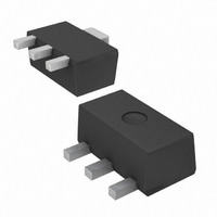
... V , REVERSE VOLTAGE (V) R Fig. 7 Typical Output Capacitance Characteristics Ordering Information (Note 5) Device DCX69-13 DCX69-16-13 DCX69-25-13 Notes: 5. For packaging details our website at http://www.diodes.com/ap02007.pdf. Marking Information Package Outline Dimensions DS31264 Rev 250 f = 1MHz 200 150 100 100 0 Fig. 8 Typical Gain-Bandwidth Product vs. Collector Current ...

Page 4

... Diodes Incorporated products are not authorized for use as critical components in life support devices or systems without the expressed written approval of the President of Diodes Incorporated. DS31264 Rev 2.7 1.3 Unit: mm IMPORTANT NOTICE LIFE SUPPORT www.diodes.com DCX69/-16/-25 © Diodes Incorporated ...

Related keywords