MD015C104JAB AVX Corporation, MD015C104JAB Datasheet
MD015C104JAB
Manufacturer Part Number
MD015C104JAB
Description
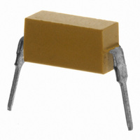
Cap Ceramic 0.1uF 50VDC X7R 5% RDL 2 Pin DIP 8.255mm Slide Pack
Manufacturer
AVX Corporation
Type
Radialr
Series
DIPGuard® MDr
Specifications of MD015C104JAB
Package/case
6.6 X 2.54(Max) X 3.43(Max)
Mounting
Through Hole
Capacitance Value
0.1 uF
Dielectric
X7R
Voltage
50 Vdc
Lead Pitch For Radial
8.255 mm
Product Length
6.6 mm
Product Height
3.43(Max) mm
Product Depth
2.54(Max) mm
Tolerance
5 %
Capacitance
0.1µF
Voltage - Rated
50V
Temperature Coefficient
X7R
Mounting Type
Through Hole
Operating Temperature
-55°C ~ 125°C
Applications
General Purpose
Package / Case
2-DIP
Size / Dimension
0.260" L x 0.100" W (6.60mm x 2.54mm)
Thickness
4.19mm Max
Lead Spacing
0.325" (8.26mm)
Voltage Rating
50 Volts
Termination Style
Radial
Operating Temperature Range
- 55 C to + 125 C
Product
General Type MLCCs
Dimensions
0.098 in W x 0.26 in L x 0.135 in H
Lead Free Status / RoHS Status
Contains lead / RoHS non-compliant
Features
-
Ratings
-
Lead Free Status / Rohs Status
No


Two Pin DIP/DIPGuard
GENERAL INFORMATION
AVX MD Series
Temperature Coefficients: C0G (NP0), X7R, Z5U,
50, 100 Volts
For established reliability DIPGuards see
MIL-PRF-39014 section on pages 57 to 62.
HOW TO ORDER
MARKING
Part Number Example
MD015 E 104MAB
AVX Style
MD01
MD01
CKR22*
CKS22**
MD02
CKR23*
CKS23*
MD03
CKR24*
CKS24**
AVX
Voltage
Y, 1, or 5
Voltage
5 = 50V
1 = 100V
A
5
5
C = X7R
A = C0G (NP0)
E = Z5U
Temperature
C = X7R
A = C0G (NP0)
E = Z5U
Dielectric
Coefficient
E
Top of Unit:
E
104
For Capacitance
First two digits are the significant
figures of capacitance. Third digit
indicates the additional number
of zeros. For example, order
100,000 pF as 104.
3 Digit Code
M
Capacitance
Tolerance
104
Code
®
PACKAGING REQUIREMENTS
Standard Packaging: MD01/MD02: 200 pieces per slide pack.
*Optional
Slide Package Dimensions
(H
(H
(H
(W
(W
(W
(W
(L) Length
C0G (NP0):
K = ±10%
F = ±1%
J = ±5%
See Table
H
O
C
I
) Inside Height
O
I
C
T
) Overall Height
) Channel Height
) Inside Width
O
) Top Width
) Overall Width
) Channel Width
NOTE 1
Note 1 = Leads centered within .010"
Note 2 = Angle shall be 95, +10, -5
H
SEE
.004
C
±.005
.025
.012
H I
Capacitance
Tolerance
X7R:
M = ±20%
K = ±10%
J = ±5%
L
M
W
W
W
W
.400 max.
T
C
I
O
NOTE 2
.035
SEE
.325
Z5U:
M = ±20%
Z = +80%
MD03: 200 pieces per vial.
20.073 ± .06 20.073 ± .06 20.073 ± .06
.141 ± .006
.400 ref.
.540 ref.
-20%
MD01
.350
.490
.210
.350
.0575 .0125
** Reference page 78.
.019 .004
* Reference pages 57 to 62.
±.002
.123 DIA. THRU 2 HOLES
60 TYP.
MAX.
.015
MIN.
A = Not Applicable
20
Failure Rate
H
1
.171 ± .006
.430 ref.
.540 ref.
MD02
A
.380
.490
.210
.310
MAX.
L
T
.028
MAX.
.148
H
.295 ± .010
2
.019 .004
.010 MAX.
A = Hand
B = Automated
Assembly
.545 ref.
.600 ref.
MD03*
Method
.495
.550
.170
.300
Assembled
Assembly
B
35
Related parts for MD015C104JAB
Image
Part Number
Description
Manufacturer
Datasheet
Request
R

Part Number:
Description:
Manufacturer:
AVX Corporation
Datasheet:
Part Number:
Description:
Manufacturer:
AVX Corporation
Datasheet:
Part Number:
Description:
Manufacturer:
AVX Corporation
Datasheet:
Part Number:
Description:
Manufacturer:
AVX Corporation
Datasheet:
Part Number:
Description:
Manufacturer:
AVX Corporation
Datasheet:
MD015C104JAB Summary of contents
Page 1
Two Pin DIP/DIPGuard GENERAL INFORMATION AVX MD Series Temperature Coefficients: C0G (NP0), X7R, Z5U, 50, 100 Volts For established reliability DIPGuards see MIL-PRF-39014 section on pages 57 to 62. HOW TO ORDER MD01 5 E AVX Style Voltage Temperature MD01 ...
Page 2
Two Pin DIP/DIPGuard SIZE SPECIFICATIONS AVX Style Length (L) 6.60 MD01 (.260 ± .020) 6.60 MD02 (.260 ± .020) 6.60 MD03 (.260 ± .020) MILITARY CROSS REFERENCE GUIDE Note: For CKR22/23/24, see MIL-PRF-39014 section in the Military Section pages 57 ...