39-3681407 Murata Power Solutions Inc, 39-3681407 Datasheet

Current Transformer 300000mA 12.5VA

39-3681407

Manufacturer Part Number
39-3681407
Description
Current Transformer 300000mA 12.5VA
Manufacturer
Murata Power Solutions Inc
Datasheet

Specifications of 39-3681407

Operating Frequency
50 to 400 Hz
Dimensions
27.9 mm W
Number Of Outputs
1
Primary Voltage Rating
600 V
Termination Style
Wire
Lead Free Status / Rohs Status
Lead free / RoHS Compliant
5A CURRENT
TRANSFORMER
General Specifications (all models)
Insulation Class
Frequency Range
Supplied Secondary
Max. Secondary Lead
Length
Rated Accuracy
Burden
UL FIle No.
CSA File No.
Weight
Leads
Basic Lightning Impulse Insulation Level (BIL): The insulation
strength referenced to the crest value of an impulse voltage-
waveform which rises to a crest value in 1.2 microseconds, then
drops to ½ the crest value in 50 microseconds.
TO AC LOAD
Figure 1. Typical Connections
 
OUTPUT
TB1
0-5A
600V, 10kV BIL full wave
50-400Hz
Flexible conductors, 24"
(61cm) 16AWG (1.8mm 2 ),
UL Style 1015, 105°C
See Table 1 and technical
note 5
See Table 1 and
technical note 6
See Table 1
E93779
LR89403
1.0 lbs. (454g)
A
B
(see technical notes)
ACA5-20PC-X-ACX
L1
AC POWER
SUPPLY
www.murata-ps.com
(CT) provide an isolated 0-5A output that can be used with DATEL’s ACA5 Series of digital
ammeters. Installation is straightforward: simply pass the load-carrying conductor through
the 5A CT’s primary window, and then route its secondary’s leads through the ACA5-amme-
ter’s built-in, low-burden, toroid sensor.
with primary voltages up to 600Vac, at line frequencies from 50 to 400Hz. Fourteen models
are available to enable accurate measurements from 50A through 2000A. When combined
with DATEL’s ACA5 Series ammeters, secondary lead-extensions may be used for those
applications where the CT cannot be installed in the immediate vicinity of the ammeter.
1. CT Precautions: In normal operation, a 5A current transformer’s secondary circuit
2. CT Connections and Grounding: Some applications require connecting one of the CT’s
3. Installation: CT’s must be installed in a manner that ensures no excessive stresses are
TECHNICAL NOTES
IMPORTANT! To ensure safe and reliable operation, Current Transformers and asso-
ciated equipment must be installed and serviced by qualified technical personnel.
Never open the CT’s secondary connections while the primary is energized. Open
CT secondary wiring can generate potentially lethal voltages when the primary cir-
cuit is energized. Contact DATEL if you have any doubts regarding the installation
or operation of any of our ac-mains measurement instruments and accessories.
operates at a relatively low voltage due to its closed-loop, low burden configuration
(essentially zero Ohms when used with DATEL’s ACA5 series ammeters). However, any
CT can generate potentially lethal voltages if its output current is suddenly interrupted. For
example, loose secondary connections can produce a condition referred to as “inductive
kick.” Inductive kick can generate extremely high voltages across the open secondary
connections.
Therefore, all connections made to a CT’s secondary leads must only be performed with
zero current flowing in the primary circuit. Never operate a CT with its secondary circuit
open and current flowing in the primary.
5A output terminals to earth/chassis ground. In the USA, consult the latest revision of the
National Electrical Code for more information.
After all mechanical assembly is completed, pass the 5A secondary leads through the
ACA5 ammeter’s built-in toroid, then connect the two leads together as shown in Figure
1. For this connection, and for connections involving lead extensions, pressure-style
connectors (commonly called “wire nuts”) are acceptable as long as they are rated for the
currents and voltages involved.
applied to the primary conductor that passes through the CT or to the secondary circuit
and its associated instruments. Use plastic tie-wraps and/or other suitable non-conductive
restraining devices to secure the CT.
These commercial grade, UL & CSA recognized, “donut style” AC current-transformers
All models feature rugged, fully insulated construction, allowing continuous operation
Technical enquiries email: sales@murata-ps.com, tel:
5 Amp AC Current Transformers
DMS Accessories
MPM_DMS-CT.A01 Page 1 of 4
+1 508 339 3000

Related parts for 39-3681407

39-3681407 Summary of contents

Page 1

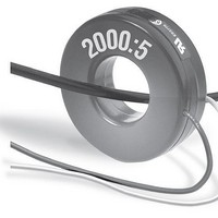
... the secondary circuit and its associated instruments. Use plastic tie-wraps and/or other suitable non-conductive restraining devices to secure the CT. www.murata-ps.com DMS Accessories 5 Amp AC Current Transformers Technical enquiries email: sales@murata-ps.com, tel: +1 508 339 3000 MPM_DMS-CT.A01 Page ...

Page 2

... Table 1’s Table 1. Selection Guide DATEL Part No. Current Ratio (Amps) 7020-01036-0 50:5 7020-01037-0 75:5 7020-01038-0 100:5 7020-01039-0 150:5 7020-01040-0 200:5 7020-01041-0 250:5 39-3681407* 300:5 39-3681408* 400:5 39-3681409* 500:5 7020-01042-0 600:5 7020-01043-0 750:5 7020-01044-0 1000:5 7020-01045-0 1500:5 7020-01046-0 2000:5 * Not RoHS Compliant burden column ...

Page 3

... Models: 7020-01036-0 – (50:5) 7020-01037-0 – (75:5) 7020-01038-0 – (100:5) 7020-01039-0 – (150:5) 7020-01040-0 – (200:5) 7020-01041-0 – (250:5) Models: 39-3681407 – (300:5) 39-3681408 – (400:5) 39-3681409 – (500:5) Models: 7020-01042-0 – (600:5) 7020-01043-0 – (750:5) 7020-01044-0 – (1000:5) 7020-01045-0 – (1500:5) 7020-01046-0 – ...

Page 4

... Murata Power Solutions, Inc. 11 Cabot Boulevard, Mansfield, MA 02048-1151 U.S.A. Tel: (508) 339-3000 (800) 233-2765 Fax: (508) 339-6356 www.murata-ps.com email: sales@murata-ps.com Murata Power Solutions, Inc. makes no representation that the use of its products in the circuits described herein, or the use of other technical information contained herein, will not infringe upon existing or future patent rights. The descriptions contained herein do not imply the granting of licenses to make, use, or sell equipment constructed in accordance therewith. Specifi ...

Related keywords