2-5435668-7 Tyco Electronics, 2-5435668-7 Datasheet - Page 3
2-5435668-7
Manufacturer Part Number
2-5435668-7
Description
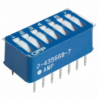
Switch DIP ON OFF SPST 7 Recessed Rocker PC Pins 2.54mm Thru-Hole
Manufacturer
Tyco Electronics
Series
7100r
Specifications of 2-5435668-7
Mounting
Through Hole
Actuator Style
Recessed Rocker
Pole Throw Configuration
SPST
Terminal Type
PC Pins
Number Of Positions
7
Contact Configuration
SPCO
No. Of Switch Positions
7
Pitch Spacing
2.54mm
Contact Current Dc Max
1A
Circuitry
SPST-CO
Switch Terminals
Through Hole
Rohs Information
2-5435668-7
Circuit
SPST
Contact Rating @ Voltage
0.06A @ 5VDC
Actuator Type
Rocker
Actuator Level
Flush
Mounting Type
Through Hole
Orientation
Top Actuated
Washable
Yes
Switch Type
DIP
Actuator
Rocker
Terminal Pitch
2.54 mm
Contact Form
SPST
Termination Style
PCB
Current Rating
0.06 A at 5 V
Operating Temperature Range
- 55 C to + 105 C
Contact Rating
0.06 A at 5 V
Lead Free Status / RoHS Status
Lead free / RoHS Compliant
Other names
450-1398


3.2. PC Board Installation
Rev B
Use Light Pressure
to Insert Switch
1. Make a layout on the pc board according to the
dimensions shown in Figure 4.
2. Make certain all contact leads have started entry
into holes. Grip sides of switch and push switch
into pc board until it is bottomed.
3. Hold switch at a slight angle and start one row
on contact leads into pc board holes. Do NOT
over--insert. Switch should be rotated until second
row of contact leads are aligned with opposite row
of contact holes.
NOTE
Protective Cover
7.62 [.300] Ref
2.54 [.100] Ref
To hold switch in place during wave soldering, the
four outside contact leads may be clinched
inward at 45. Refer to Figure 5.
Figure 3
Figure 4
NOTE: These same procedures
apply to socket installation.
Grip Here
Rotate to Align Second
Row - - Then Push Down
on Ends of Switch
Cover Latch
4. SWITCH PROGRAMMING
After the switch has been inserted into the DIP socket
or soldered onto the pc board, proceed as follows:
Housing Bottomed
on PC Board
Remove Seal from Top
Left to Bottom Right
(Diagonal Across the
Switch)
Remove Tape
Seal from
End
NOTE
1. Remove seal from the switches, see Figure 6.
For pc board soldering and cleaning procedures,
and recommended solvents, refer to Application
Specification 114- - 1056.
Clinched Contact Lead (Inward Only)
Figure 5
Figure 6
Low- - Profile Switch
Masking Material
Seal
Standard- - Profile or
Side- - Actuated Switch
PC Board
408- 7779
3 of 4
Related parts for 2-5435668-7
Image
Part Number
Description
Manufacturer
Datasheet
Request
R

Part Number:
Description:
High Speed / Modular Connectors HDI RECP ASSY 3 ROW 1197
Manufacturer:
TE Connectivity
Datasheet:

Part Number:
Description:
Conn Socket Strip RCP 54 POS 2.54mm Solder ST Thru-Hole
Manufacturer:
Tyco Electronics
Datasheet:
Part Number:
Description:
HDI PIN ASSY 3 ROW 54 POS
Manufacturer:
Tyco Electronics
Datasheet:

Part Number:
Description:
54 MODII HDR DRST UNSHRD STKG
Manufacturer:
TE Connectivity
Datasheet:

Part Number:
Description:
CONN HEADER 54POS DL .100 15GOLD
Manufacturer:
Tyco Electronics
Datasheet:
Part Number:
Description:
BARRIER STRIP 27POS .375
Manufacturer:
Tyco Electronics
Datasheet:
Part Number:
Description:
CONN BARRIER BLOCK 27POS 9.53MM
Manufacturer:
Tyco Electronics
Datasheet:

Part Number:
Description:
TERMINAL,PIDG R IR 14 3/8
Manufacturer:
TE Connectivity
Datasheet:
Part Number:
Description:
CONN HDI RECEPT 54POS 3ROW R/A
Manufacturer:
Tyco Electronics
Datasheet:
Part Number:
Description:
CONN RECEPT 54POS .100 VERT DUAL
Manufacturer:
Tyco Electronics
Datasheet:
Part Number:
Description:
Restricted Automotive V23540B1626F510=26P ELO-STECKE
Manufacturer:
Tyco Electronics
Part Number:
Description:
Electromechanical Relay SPDT 20A 12VDC 270Ohm Through Hole
Manufacturer:
Tyco Electronics
Datasheet:
Part Number:
Description:
Electromechanical Relay SPST-NO 10A 24VDC 3.39KOhm Through Hole
Manufacturer:
Tyco Electronics
Datasheet:
Part Number:
Description:
Conn IDC Connector RCP 10 POS 2.54mm IDT RA Cable Mount
Manufacturer:
Tyco Electronics
Datasheet: