G6L1FDC12 Omron, G6L1FDC12 Datasheet
G6L1FDC12
Specifications of G6L1FDC12


Related parts for G6L1FDC12

G6L1FDC12 Summary of contents
Page 1
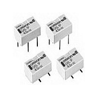
... Low Signal Relay G6L Extremely Thin SPST-NO Flat Relay, One of the Thinnest Relays in the World • Uses 20% less mounting area and 67% less volume in comparison with the G5V-1 relay. • Measures just 7.0 (W) x 10.6 (L) x 4.5 (H) mm for surface- mount or 4.1 (H) for through-hole. ...
Page 2
Specifications ■ Contact Ratings Item Contact mechanism Rated load Carry current Max. operating voltage Max. operating current Min. permissible load - P level (See note) Note: This value was measured at a switching frequency of 120 operations/min. This value may ...
Page 3
... Z Y' Sample: G6L-1F Z' Number of Relays Conditions: Shock is applied in ±X, ±Y, and ±Z directions three times each with and without energizing the Relays to check the number of contact malfunctions. Contact Reliability Test (Contact Resistance) (See notes 1 and 2) 1,000 Sample: G6L-1F NO contact Number of Relays: 10 ...
Page 4
... Frequency (MHz) (Average value) + +20 +10 0 −10 −20 Must operate voltage Sample: G6L-1F Must release voltage Number of Relays: 5 −30 −1,200 −800 −400 0 400 800 1,200 External magnetic field (A/m) (Average value) 0 1.4 V.SWR 1.2 1 Return loss 0.8 0.6 0.4 0.2 ...
Page 5
... PCB Mounting Holes (Top View) Tolerance: ±0 ±0.2 ±0.2 0.4 8.4 1.49 5.08 0.8 Vibration Resistance 5.0 Sample: G6L-1F Number of Relays: 5 4.0 3.0 2.0 1.0 Must release voltage 0.0 -1.0 Must operate voltage -2.0 -3.0 -4.0 -5.0 Initial After test ...
Page 6
... No. of Relays per tube: 50 ■ Tape and Reel Packaging (Surface-mount models) When ordering Relays in tape and reel packaging, add the suffix “-TR” to the model number, otherwise the Relays in tube packing will be provided. • Tape type: TB2412R (Refer to EIAJ (Electronic Industries Association of Japan) • ...
Page 7
... UL Recognized (File No. E41515) / CSA Certified (File No. LR31928 Ambient Temp. = 40°C Contact form SPST-NO G6L-1P and G6L-1F VDC The thickness of cream solder to be applied should be within a range between 150 and 200 μm on OMRON's recommended PCB pattern. Correct Soldering Relay Terminal PCB Visually check that the Relay is properly soldered. ...
Page 8
... Coating Relays mounted on PCBs may be coated or washed. Do not apply silicone coating or detergent containing silicone, otherwise the sili- cone coating or detergent may remain on the surface of the Relays. Coil Power Supply Waveform If the voltage applied to the coil is increased or decreased gradually, operating characteristics may be unstable, contact endurance may decline, or the Relay may not function at its full performance level ...
Page 9
... Seller within 30 days of receipt of shipment. III. PRECAUTIONS 1. Suitability THE BUYER’S SOLE RESPOINSIBILITY TO ENSURE THAT ANY OMRON PRODUCT IS FIT AND SUFFICIENT FOR USE IN A MOTORIZED VEHICLE APPLICATION. BUYER SHALL BE SOLELY RESPONSIBLE FOR DETERMINING APPROPRIATENESS OF THE PARTICULAR PRODUCT WITH RESPECT TO THE BUYER’ ...
Page 10
... THE OMRON PRODUCT IS PROPERLY RATED AND INSTALLED FOR THE INTENDED USE WITHIN THE OVERALL EQUIPMENT OR SYSTEM. Complete “Terms and Conditions of Sale” for product purchase and use are on Omron’s website at http://www.components.omron.com – under the “About Us” tab, in the Legal Matters section. ...